Some cool precision components engineering photos:
Dismal Swamp Canal continues 85-year revival
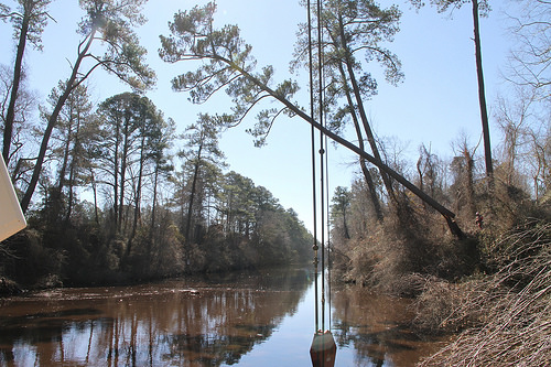
Image by norfolkdistrict
The crew of the U.S. Army Corps of Engineer’s vessel Elizabeth operate in tandem March 11, 2014, to down unsafe, leaning pine trees that will be employed to reinforce and stabilize the banks along the Dismal Swamp Canal. Two trees in the background will also be downed to safeguard navigation along the DSC.
On March 30, 1929, the U.S. federal government purchased the Dismal Swamp Canal for ,000, soon after a protracted period of neglect and common decay by private ownership, worsened by advances in modes of transportation. In the ensuing years, the U.S. Army Corps of Engineers, which operates and maintains America’s oldest continually operating man-made canal, has replaced the locks of 1899 with new steel and concrete locks, along with a lot of other navigational improvements.
The crew of Norfolk District’s vessel Elizabeth makes use of an ND-6, 112-foot crane barge to snag and get rid of debris, shore up canal banks by removing tree limbs and underbrush, and cut down harmful, leaning trees that could impede the secure and effective navigation along the 33-mile stretch of the DSC.
The Dismal Swamp Canal, which meanders via North Carolina and Virginia, is element of the Atlantic Intracoastal Waterway, a key inland protected route for commercial vessel traffic from Norfolk, Va. to Miami, Fla.
The crew of the Elizabeth: Richard Bruton, captain, Dennis Barnes, master crane operator, Glen Boykin, marine mechanic, and Erik Sherer, deckhand, have been functioning all week to clear the canal, soon after a recent winter storm swept via the area.
“Richard and I have been sustaining the DSC for 25 years,” said Barnes. "Along with Glen and Erik, our crew functions like a fine-tuned, precision engine. We strongly think in and practice the ‘t-e-a-m’ in teamwork –Together…Earn…Achieve…More.” (U.S. Army photo/Gerald Rogers)
Image from page 585 of “Railway mechanical engineer” (1916)
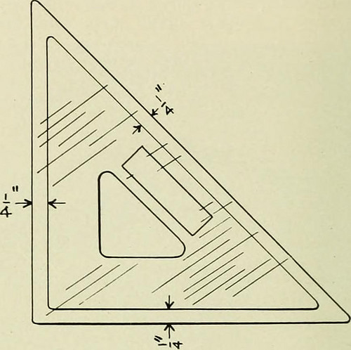
Image by Internet Archive Book Images
Identifier: railwaymechanica90newy
Title: Railway mechanical engineer
Year: 1916 (1910s)
Authors:
Subjects: Railroad engineering Engineering Railroads Railroad automobiles
Publisher: New York, N.Y. : Simmons-Boardman Pub. Co
Contributing Library: Carnegie Library of Pittsburgh
Digitizing Sponsor: Lyrasis Members and Sloan Foundation
View Book Web page: Book Viewer
About This Book: Catalog Entry
View All Images: All Images From Book
Click right here to view book on-line to see this illustration in context in a browseable on the web version of this book.
Text Appearing Just before Image:
Tool for Truing Grinding Wheels.—The diamond tool is the most effective implies for truing theface of grinding wheels for precision perform so far found.The motives are: Diamonds or bortz are harder than thewheel to be trued they are obtainable in sufficient quantitiesto meet the demand: they give a signifies of producing thewheel a true cylinder and at the same time provide anykind of wheel service preferred they lend themselves to areasonably easy setting and are conveniently applied to thework, and the waste of the wheel is negligible.—Grits andGrinds. TRIANGLE FOR USE IN TRACING BY HUGH G. BOUTELL The accompaning sketch shows a triangle which was de-veloped by the writer and has proved particularly helpful intracing operate where speed is important. It is made up of two45-deg. triangles, 1 sufficient bigger than the other so thatit projects about J4 in- on all 3 sides. The two trianglesare held collectively with Le Pages glue. In tracing, considerable care is required to slide an ordi-
Text Appearing After Image:
Convenient Triangle for Use in Tracing nary triangle up to a freshly inked line with out touching thewet ink. In the double triangle, the j4-in. projection of theupper part obviates the danger of blotting the tracing. Italso makes it possible for higher lateral freedom of the ruling pen andmakes feasible greater matching up of straight lines andcurves. Railroad Coal Consumption.—The railroads of theUnited States utilized 128,200,000 net tons of coal in 1915.This amounts to about 24 per cent of the total output. Thebituminous mines furnished 122,000,000 tons, which is 28per cent of their production, and the Pennsylvania hard coalregions supplied six,200,000 tons, approximately 7 per centof the total production. Size of Steam Pipes for Reciprocating Engines.—Size of steam pipes for reciprocating engines operating atfull stroke could be determined by comparing the diameterof the cylinder squared and multiplied by the piston speedper minute with the diameter, assumed, for the steam pipesquared and multiplied
Note About Photos
Please note that these photos are extracted from scanned web page pictures that might have been digitally enhanced for readability – coloration and look of these illustrations may not perfectly resemble the original perform.
Image from web page 1147 of “Electrical planet” (1883)
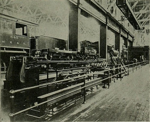
Image by Web Archive Book Pictures
Identifier: electricalworld43newy
Title: Electrical world
Year: 1883 (1880s)
Authors:
Subjects: Electrical engineering
Publisher: [New York McGraw-Hill Pub. Co., and so forth.]
Contributing Library: Engineering – University of Toronto
Digitizing Sponsor: University of Toronto
View Book Page: Book Viewer
About This Book: Catalog Entry
View All Images: All Photos From Book
Click right here to view book on the internet to see this illustration in context in a browseable on the web version of this book.
Text Appearing Ahead of Image:
or belt ordirect connection rotary converters, motor-generator sets, oil-in-sulated and air-blast transformers, direct-existing and alternating-existing railway motors and controllers, single and polyphase in-duction motors of constant and variable speeds, direct-current motorsof several types, which includes motors for variable-speed service fromsingle and double-voltage circuits, switchboard apparatus, ammeters,voltmeters, wattmeters, synchroscopes, power issue meters, circuit-breakers and switches, a lot of of them electrically operated portableinstruments, instruments of precision, possible regulators, and innu-merable other forms of auxiliary apparatus and instruments. Thealternating-existing, series-wound, single-phase crane motors, sim-ilar in sort and general construction to the single-phase railwaymotors exhibited in the Transportation Building, and the new West-inghouse Unit Switch Technique of Numerous Handle are also to heseen in this section. The spectacular high-tension sign, making use of a
Text Appearing Following Image:
FIG. 5.—BRAKE E.XHIBITS, TRANSPORTATION Creating. brake which is now so significantly in use. The strategy at present gen-erally adopted when two pumps are employed on one locomotive isshown, and a single of the novel attributes of the rack is that all valvesare placed ig duplicate, one sectioned so as to show the internalworking mechanism, and connected to the valve in use in such a ELECTRICAL Planet and ENGINEER. Vol. XLIII, No. 24. manner that it moves as the regular valve is operated. The opera-tion of the different valves is therefore readily studied. The Westinghouse friction draft gear also is shown in section,with a machine specifically made for testing it in operation. Theavailable power which can be e.xerted on the draft gear approximates2,000 pounds. A triple valve testing rack is presented to show themanner in which this device is now becoming installed in a lot of rail-road shops. Sectional components also are shown of the other apparatusof the Westinghouse Air Brake Firm and the WestinghouseTraction Brake
Note About Pictures
Please note that these pictures are extracted from scanned web page images that could have been digitally enhanced for readability – coloration and appearance of these illustrations may possibly not completely resemble the original function.