Cool Precision Component Producers pictures

Cool Precision Component Producers pictures

A handful of nice precision element makers photos I found:

Apollo 14 Docking Ring
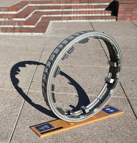
Image by jurvetson
Milled from a solid block of titanium, with twelve docking latches, it is a marvel of precision design and style in the era ahead of CAD/CAM.

The Smithsonian believed this was the CM docking ring from Apollo 14 Command Module, and had paperwork to help that. I feel it is the sister unit, a big structural engineering element utilised for ground testing to try to recreate the series of docking failures seasoned early in the Apollo 14 mission with the probe that was brought back (normally the docking probe would be left behind). Hence the Apollo 14 label on the base and description at the Bonhams’ auction:

NASA’s choice to fly Apollo missions employing a lunar orbit rendezvous approach necessary the improvement of a method to join, separate, then rejoin two spacecraft. This system also had to let astronauts to move internally between the Command and Lunar Modules. The flight configuration selected was an effect system consisting of a probe situated at the forward end of the Command Module (CM) and a funnel-kind drogue located at the prime of the Lunar Module (LM). The CM’s probe was mounted to the docking ring, which provided a point of structural integrity for the two docked cars as soon as the probe was removed. Removal of the probe produced a tunnel so the crew could travel between the docked cars. A series of latches about the docking ring locked the cars collectively. The tip of the probe had a set of 3 modest capture latches which had been developed to hold the vehicles with each other lengthy adequate that the bigger docking ring latches could be engaged.

Just right after the Saturn V’s third stage sent Apollo 14 on its planned trajectory toward the moon, Shepard along with astronauts Edgar Mitchell and Stuart Roosa seasoned difficulty docking the CSM to the LM. 5 attempts were created but the docking probe capture latches never engaged to secure the two cars together. This could have scrubbed for the second time in a row a lunar landing mission. With the failure of Apollo 13 due to a Service Module oxygen tank explosion, a scrub of the Apollo 14 lunar landing would most definitely have offered ammunition to these in Congress lobbying for an early termination of the Apollo Plan.

Soon after practically two hours of delays and on the sixth try, with Roosa holding the CSM tight with the LM for many seconds, the latches lastly engaged. The crew then activated the series of larger latches mounted along the docking ring to receive a &quothard dock&quot configuration. Though they had been ultimately docked, Mission Manage and the crew’s concern shifted to the possibility that the program could fail when it was most necessary, the redocking of the LM Ascent Stage following Shepard and Mitchell’s return from the moon. If this happened the crew could be forced into performing a space walk in order to return to the CSM. The lunar rocks and scientific data may well have to be abandoned in the LM pending the precise situations of a possible lunar orbit docking problem. The probe was completely inspected by the crew throughout the coast period to the moon and they sent detailed verbal descriptions plus television pictures to Mission Control. Because the probe now showed standard operation of the capture mechanism, NASA created the selection to proceed with the planned mission.

The redocking while in lunar orbit was fully normal. The docking probe (usually jettisoned with the LM) was returned to earth for inspection and evaluation.

NASA and spacecraft manufacturer North American Rockwell performed an exhaustive series of tests to the docking system. All elements (probe, latches, docking ring) had been tested &quotin location&quot with the recovered Apollo 14 CM, then each was removed for a series of combined and person tests. The docking method dilemma was a major reason the docking ring was removed and never ever re-installed into the Apollo 14 CM. Post-flight evaluation of tv, motion image film, accelerometer info, and reaction control system thruster activity indicated that probe-to-drogue get in touch with conditions were as expected for all docking attempts. The probe’s capture latches should have worked on every of the 1st 5 docking attempts. A plunger-variety component in the capture latch failed to reach a forward or locked position most likely due to some kind of foreign debris or contamination. A change in the size of the plunger due to temperature was an added possibility. Internal harm to the capture-latch mechanism was ruled out as the cause because the program functioned correctly in all subsequent operations following the sixth docking try and throughout post flight testing. The debris or contamination most probably became dislodged following the fifth docking try, enabling the system to operate effectively from that point. NASA and Rockwell created the decision to supply a protective cover on the tip of the probe to prevent contamination during future flights.

Throughout the tests, the ring was shipped between a variety of NASA and contractor facilities through a 39 by 39 by 12 inch wood transit case which is integrated with the ring. The ring itself has a series of inspection stamps and ID numbers that study: &quotMDR 408699, V36-316250-9, 06361-B009522, MR 361588, DEC 9 1968, V36 316250 31, ASSEM, FEB 18 1969, 06361A015194.&quot A separate 6 by 3 inch yellow &quotTemporary Parts Removal Tag&quot repeats many of these numbers and has the added hand-written information of: &quotTPS 112, REM #103, Docking Ring, S/C 110, 2/14/72.&quot

Included are copies of documents listing the NASA artifact number (2243) getting from Command Module (S/C # 110) for the transfer to the National Air and Space Museum (NASM) and deascession papers from NASM.

The Apollo 14 docking ring is the single biggest and heaviest piece of lunar spacecraft structural gear ever to be provided to private hands. The flown CM docking ring, the twin of this one particular, remained with the ascent stage of the Lunar Module Antares when it was jettisoned. Antares was then deliberately crashed into the moon’s surface to simulate a &quotmoonquake.&quot

VLEDs Expands Line of High-Quality Fog Lights

VLEDs Expands Line of High-Quality Fog Lights


Bellingham, Washinton (PRWEB) August 30, 2014

Security and style are now synonymous—VLEDs has fog lights of all sizes and types for just about any auto, van, or truck. Sturdy, extended-lasting, and sophisticated, VLEDs’ fog lights are impressive and can make a wonderful addition to any vehicle.

&#13

A lot of buyers locate it frustrating when they buy a new vehicle and the lights do not match. Sure, the headlights may possibly appear excellent, but the fog lights are ugly and yellow. This happens typically, even with the newest 2014 and 2015 models. For example, the daytime operating lights and fog lights for all Cadillac models are characterized by their unsightly yellow light. Cadillac is not alone there—many other tends to make have this issue. That is why buyers turn to VLEDs in order to get safety and style in equal proportions. VLEDs enables auto owners to transform their regular, hum-drum vehicles into higher-end, fashionable machines with LED fog lights of every size.

&#13

For example, VLEDs gives the CREE MT-G2 Higher Power LED Headlights. The MT-G2 involves two CREE MT-G2 higher-energy LEDs that emit an definitely astonishing light output, even in the heaviest fog. The MT-G2 installs in minutes, virtually immediately transforming a automobile, providing it a excellent new appear while boosting its safety level.

&#13

VLEDs also consists of a lot of other best-rated LED fog lights in its substantial catalog. Sizes consist of H1, H9, H8, 9145, and 9006, just to name a couple of. As always, VLEDs components come with a generous warranty.

&#13

About VLEDs

&#13

Founded in 2005 in Bellingham, Washington, VLEDs has quickly become 1 of the largest suppliers of automotive LED and HID lights in the globe. VLEDs delivers an incredible array of bulb types, from headlights, fog lights, brake lights, and license plate lights to lights for turn signals, festoon dome vanities, parking markers, and instrument gauges, as nicely as numerous other components.

&#13
&#13
&#13
&#13
&#13

Motorcyle enthusiast Custom Machined Parts

Motorcyle enthusiast Custom Machined Parts

CNC machined Items http://www.floydfolks.org & http://www.littlefamilyfarm.com 1-540-745-2322 floydlcfgroup@gmail PO box 179 Floyd,Virginia 24091 follow u…
Video Rating: 5 / five

Fitzpatrick Manufacturing Company is a custom CNC machine shop that tends to make the most complex components with ease thanks to a highly educated employees, state of the art…
Video Rating: five / 5

Most recent Precision Engineering Components News

Grinding back lead instances
Up till recently Helander had sub-contracted any grinding operate that it needed performing, but this changed when it invested in a couple of second hand grinders to fulfil a contract for a client in the oil &amp gas sector for elements with carbide embedded&nbsp…
Read far more on Engineering Capacity

Interview: A new way to recognize the human brain
Opsins can be engineered for diverse properties, including improved radiance, the level of which tracks the membrane voltage changes with high temporal precision. We used directed evolution of opsins … slow, tedious, costly and error prone. We …
Study far more on Forum:Blog (blog)

Spin Casting And Rapid Prototype Technology

Spin Casting And Rapid Prototype Technology

Spin Casting has brought rapid prototype technologies to a totally various level of production efficiency. With the capability of making prototypes in distinct metals spin casting has provided firms alternatives in no way just before experienced in speedy prototype methods. Now with spin casting technology fragile, functional metal parts can be manufactured with speedy prototype models.

Spin casting can cut production instances by a considerable percentage and have prototypes accessible for testing the same day as production. The spin casting technology also eliminates the need to have for considerable post production tooling and refinishing. Spin casting technology is also effortless to use with all the custom characteristics required to generate even complex design specifications.

Spin Casting Fabrication Metals

Spin casting technologies can accommodate a quantity of metals to produce fine quality prototypes that are completely functional and created according to design and style specifications. Employing rubber molds a variety of metals can be utilized with spin casting technologies to produce a variety of finished products. Spin casting can create prototypes consisting of zinc alloys which are a favored casting metal, as these metals can accept a selection of surface finishing compounds. These alloys are frequently utilised in spin casting to replace aluminum, copper and low-grade steel. Spin casting prototypes are suitable for electroplating to generate the look of brass, silver or gold.

Spin casting can also produce prototypes in many other types of materials as effectively. Utilizing polyurethane, polyester, epoxy or wax spin casting can generate a quantity of items in a selection of supplies. Comparing the production cost of spin casting and conventional tooling has spin casting as the most expense effective strategy of production. Spin casting can create the exact same products as traditional tooling and molds but for a fraction of the price. With spin casting an additional feature is be able to manage the number of products manufactured. With classic manufacturing, single or tiny item orders are typically a lot more expensive with prices decreasing as unit numbers enhance. But spin casting expenses remain steady throughout the production procedure regardless of the quantity of items made producing it quite price efficient.

Spin Casting Fabrication Actions

Spin casting needs the use of molds that are made from a silicone based material and can accommodate the original components to form precise information of the models used in production. As soon as ready the spin casting molds are hardened and the models are removed leaving detailed molds that will be utilised for prototype production. With spin casting temperatures reaching about 400C air vents are reduce into molds to let gases to escape in the course of the production procedure. Spin casting uses centrifugal force to inject fabrication material into molds guaranteeing all particulars of the model are reproduced in the prototype. Spin casting permits for comprehensive adjustment of production speeds, pressure controls and cycle times. Prototypes produced by spin casting are precision merchandise that will meet all design and style specifications and tolerances.

Spin casting cuts the time needed to create fast prototype by a considerable amount and will have prototypes offered for the testing phase in a shorter amount of time. Spin casting technologies can assistance post production finishing by becoming in a position to use a wide variety of materials. Spin casting strategies are easy to use, expense powerful and a time conserving technology for the production of rapid prototypes.

We are delivering specialist precise rapid manufacturing,prototype rapid,3d prototype, plastic prototype,3d prototyping,3d rapid prototyping,plastic prototyping,speedy tooling and speedy prototype in China. We look forward to participating at the achievement of your subsequent project.