A few nice precision engineering elements images I identified:
Steven F. Udvar-Hazy Center: Kawanishi N1K2-Ja Shiden Kai “George”
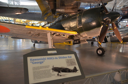
Image by Chris Devers
See a lot more photos of this, and the Wikipedia report.
Particulars, quoting from Smithsonian National Air and Space Museum: Steven F. Udvar-Hazy | Kawanishi N1K2-Ja Shiden (Violet Lightning) Kai (Modified) "GEORGE":
GEORGE is the unlikely Allied nickname for the very best Japanese naval fighter developed in quantity throughout World War II. The official Japanese name and designation was Kawanishi N1K2 Shiden (Violet Lightning). This outstanding land-based fighter sprang straight from a floatplane fighter design, the N1K1 REX (see NASM collection).
Many countries utilized floatplanes for scouting and reconnaissance duties, and to hunt submarines and surface ships, but only Japan built and fielded fighters on floats. The Japanese Imperial Navy intended to use these specialized aircraft to achieve air superiority above a beachhead to assistance amphibious landing operations exactly where carrier or land-based fighters had been unavailable. The Kawanishi N1K1 (Allied codename REX) was the only airplane made especially for this purpose to fly in the course of Planet War II.
In September 1940, the Japanese Navy issued a specification for floatplane fighters capable of supporting offensive naval operations. A team of engineers like Toshihara Baba, Shizuo Kikuhara, Hiroyuki Inoue, and Elizaburo Adachi had readied the initial prototype by Might 1942, and it flew on Might 6. Tests showed that the speed of new airplane was only slightly less than the Mitsubishi A6M Zero (see NASM collection) and the amphibious fighter was virtually as maneuverable as its land-primarily based cousin. This was remarkable efficiency for an aircraft that could not retract or jettison its enormous landing gear.
Extended just before the very first Kyofu flew, Kawanishi engineers believed that the fundamental style would also make an excellent land-based fighter. The conversion appeared to entail basically replacing the major and wingtip floats with a traditional landing gear. The business decided to develop this variant as a private venture. As the project unfolded, the engineers decided to replace the 14-cylinder engine with a new 18-cylinder model anticipated to create about two,000 horsepower. The new engine essential a bigger propeller and this component, in turn, necessary abnormally lengthy landing gear struts to stop the blade ideas from contacting the ground. Kawanishi flew the initial N1K1-J land-primarily based fighter on December 27, 1942. The new engine failed to deliver the anticipated power and the landing gear functioned poorly. The airplane also fell quick of projected speed (649 kph – 403 mph) by 74 kph (46 mph) and could handle only 575 kph (357 mph). This was more rapidly than the Mitsubishi A6M Zero ZEKE, nonetheless, and the Japanese Navy badly required an powerful counter to new American naval fighter aircraft such as the Grumman F6F Hellcat and Vought F4U Corsair (see NASM collection). The Japanese Navy ordered Kawanishi to abandon two other fighter projects and start building Shidens.
By the end of 1943, Kawanishi delivered about 70 of the new fighters and the Navy employed these airplanes for pilot familiarization and coaching. Expecting Allied amphibious landings in the Philippines, the Navy sent the very first Shiden unit to Cebu in time to challenge Allied air energy supporting the invasion of that island in October 1944. Engine, landing gear, logistics, and upkeep issues plagued the Shiden units but Allied pilots realized they faced a excellent new Japanese fighter.
With N1K1-J production underway and Shidens flying combat missions, Kawanishi set about refining the design. They lowered the wings from mid-fuselage and the extra ground clearance permitted the engineers to install a shorter, much more conventional and less-troublesome landing gear, simplified the fuselage structure, and redesigned the empennage. Only the wings and armament remained from the initial design. The engine continued to give problems, but the Navy was impressed with these improvements and ordered the new version into production as the N1K2-J Shiden Kai (modified). In air-to-air combat, seasoned Japanese pilots flying Shiden Kais could much more than hold their personal against most American pilots flying F6F Hellcats. In February 1945, a brave pilot, Warrant Officer Muto, single-handedly engaged 12 Hellcats and shot down four of them before the remainder disengaged. Flying intercept missions against Boeing B-29 Superfortresses above the residence islands, the Shiden Kai was less effective since of inadequate climb speed and energy loss at high altitudes.
Kawanishi developed a number of other variants and planned a lot more when the war ended. About 1,500 of the various models had been created. In battle over Formosa (Taiwan), the Philippines, Okinawa, and the house islands, Shiden pilots acquitted themselves nicely but this superb airplane was yet another very good design and style that appeared too late and in as well few numbers to reverse Japan’s fortunes in the air war.
NASM’s Shiden Kai is one of 3 remaining today. The other two are displayed at the U. S. Air Force Museum in Dayton, Ohio, and the New England Air Museum in Windsor Locks, Connecticut. American intelligence units collected 4 GEORGE fighters from numerous Japanese airfields and delivered them to Yokosuka Naval Shipyard for shipment to the United States. The NASM GEORGE came from Omura or Oppama Naval Air Station, Japan, and the fighter arrived stateside aboard the escort carrier "USS Barnes." It was probably evaluated at the Naval Aircraft Factory at Philadelphia, and then moved to Willow Grove Naval Air Station. The GEORGE remained outdoors on show and steadily deteriorated along with a group of German and Japanese airplanes till 1983 when the Smithsonian Institution acquired it. The airplane was stored at the Paul Garber Facility until NASM loaned it to the Champlin Fighter Museum in Mesa, Arizona, for restoration in December 1991 and the project was completed in November 1994. The restored Shiden Kai wears the colors and markings of the 343rd Kokutai, a unit stationed at Omura Naval Air Station in 1945.
Transferred from the United States Navy.
Manufacturer:
Kawanishi Kokuki K. K.
Date:
1942
Nation of Origin:
Japan
Dimensions:
Overall: 400 x 930cm, 2675kg, 1200cm (13ft 1 1/2in. x 30ft 6 1/8in., 5897.3lb., 39ft four 7/16in.)
Components:
All-metal monocoque construction
Physical Description:
Single-engine, low-wing monoplane, standard layout with tailwheel landing gear.
Image from page 241 of “The Bell Technique technical journal” (1922)
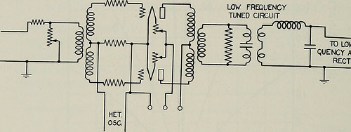
Image by Net Archive Book Images
Identifier: bellsystemtechni06amerrich
Title: The Bell Program technical journal
Year: 1922 (1920s)
Authors: American Phone and Telegraph Company
Subjects: Telecommunication Electric engineering Communication Electronics Science Technologies
Publisher: [Brief Hills, N.J., etc., American Phone and Telegraph Co.]
Contributing Library: Prelinger Library
Digitizing Sponsor: Web Archive
View Book Web page: Book Viewer
About This Book: Catalog Entry
View All Images: All Images From Book
Click right here to view book on the web to see this illustration in context in a browseable on the web version of this book.
Text Appearing Ahead of Image:
partially eliminatelarge interfering currents. This appears a most unusual arrangementuntil it is remembered that, despite the fact that the amplitude of a particularpart of the current may be elevated, the total load on the first stagemay nicely be higher than that on the final stage. This is the reverseof the scenario in cascade amplification where the first tubes handleonly a modest existing and the succeeding ones a proportionately largercurrent. The discrimination of a single of the tuned circuits when a couplingresistance of 1 ohm is utilized is provided by curve A of Fig. 4. Curve Bshows the effect of adding the second tuned circuit. If regenerativeamplification had been employed, each the selectivity and amplificationcould of course be significantly enhanced, but this has not been utilised becauseof the necessity for higher stability and measurement precision. Modulator. As previously mentioned, the second amplifier unitworks into a modulator, the circuit of which is shown in Fig. 5. This is LOW FREQUENCYTUNED CIRCUIT
Text Appearing Right after Image:
TO LOW FRE-QUENCY AMPLIFIER-RECTIFIER Fig. 5—Modulator for heterodyne current analyzer of a two tube balanced type In which modulation, or frequency trans-formation, takes spot in the grid circuit. The heterodyning fre-quency is applied in the frequent input lead across a suitable resistance.The input from the amplifier is applied via a transformer acrossthe grids of the two tubes in series with a high resistance in each and every side.No biasing possible is applied on the grids. A modulator operated inthis manner has the house of providing a modulation output propor-tional to the smaller sized of the two input currents and independent of thelarger. The amplitude of this output may possibly, as a result, be determinedentirely by the amplitude of the element becoming measured. Anotherdesirable characteristic of this kind of modulator is that its efficiency isnot affected by interference, therefore it will show a fixed relation among ANALYZER FOR Complex ELECTRIC WAVES 237 the low frequency output and a offered
Note About Photos
Please note that these photos are extracted from scanned page photos that may possibly have been digitally enhanced for readability – coloration and appearance of these illustrations may possibly not perfectly resemble the original operate.