Check out these high precision engineering images:
Steven F. Udvar-Hazy Center: primary hall panorama (P-40 et al)
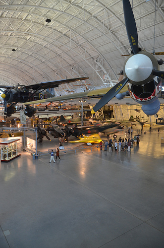
Image by Chris Devers
See a lot more images of this, and the Wikipedia write-up.
Details, quoting from Smithsonian National Air and Space Museum | Curtiss P-40E Warhawk (Kittyhawk IA):
Whether identified as the Warhawk, Tomahawk, or Kittyhawk, the Curtiss P-40 proved to be a effective, versatile fighter for the duration of the initial half of Planet War II. The shark-mouthed Tomahawks that Gen. Claire Chennault’s "Flying Tigers" flew in China against the Japanese remain amongst the most popular airplanes of the war. P-40E pilot Lt. Boyd D. Wagner became the 1st American ace of Planet War II when he shot down six Japanese aircraft in the Philippines in mid-December 1941.
Curtiss-Wright built this airplane as Model 87-A3 and delivered it to Canada as a Kittyhawk I in 1941. It served till 1946 in No. 111 Squadron, Royal Canadian Air Force. U.S. Air Force personnel at Andrews Air Force Base restored it in 1975 to represent an aircraft of the 75th Fighter Squadron, 23rd Fighter Group, 14th Air Force.
Donated by the Exchange Club in Memory of Kellis Forbes.
Manufacturer:
Curtiss Aircraft Company
Date:
1939
Nation of Origin:
United States of America
Dimensions:
General: 330 x 970cm, 2686kg, 1140cm (10ft 9 15/16in. x 31ft 9 7/8in., 5921.6lb., 37ft 4 13/16in.)
Materials:
All-metal, semi-monocoque
Physical Description:
Single engine, single seat, fighter aircraft.
Image from web page 548 of “The Bell Method technical journal” (1922)
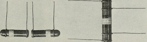
Image by Internet Archive Book Pictures
Identifier: bellsystemtechni19amerrich
Title: The Bell Program technical journal
Year: 1922 (1920s)
Authors: American Phone and Telegraph Business
Subjects: Telecommunication Electric engineering Communication Electronics Science Technologies
Publisher: [Quick Hills, N.J., etc., American Phone and Telegraph Co.]
Contributing Library: Prelinger Library
Digitizing Sponsor: Web Archive
View Book Web page: Book Viewer
About This Book: Catalog Entry
View All Photos: All Images From Book
Click here to view book on-line to see this illustration in context in a browseable online version of this book.
Text Appearing Ahead of Image:
RTZ CRYSTAL FILTERS 525 pregnated and potted in wax. A molded jacket with protruding fins,placed around the core, reduces the capacitance from windings to coreand improves the uniformity of the windings. The coils are adjustedto inside ± 1 per cent for inductance and two per cent for inductanceunbalance by removal of excess turns, all adjustments becoming made atlow frequency. Figure 7 shows a coil at this stage of manufacture. The coil is then potted in a copper can and a cover soldered in place.Final test simulates actual service conditions. The coil is resonatedwith an external variable condenser at the operating frequency forwhich it is developed. Condensers Practically all crystal filters include condensers shunted across thecrystal components. These condensers should meet stability requirementssimilar to these currently talked about in connection with coils. A single type of fixed condenser, utilized exactly where small values of capacitanceand high stability are needed, is illustrated in Fig. eight. Silver is fused
Text Appearing Soon after Image:
Fig. 8—Silvered glass condensers employed in crystal filter applicationswhere high stability is essential. to the inside and outside of a glass tube by applying a coating of silverpaste and firing the tube in an oven. A gap is left uncoated on theouter surface near the open end and leads are soldered to the silver onboth sides of the gap. The capacitance is then adjusted to the re-quired value, within about ±1.5 mmf., by scraping off a portionof the silver coating. Capacitances up to 80 mmf. are realized by thismeans. Two condensers might be combined in a single unit, as shownat the proper in Fig. 7. The completed condenser is dipped in varnishto safeguard the silver from corrosion. Pairs of such condensers, matched to every single other within .4 mmf., arerequired in some varieties of crystal filters. This precision is achieved bymanufacturing a quantity of condensers of the right nominal capaci-tance and sorting them into close-limit groups following final measurement. 526 BELL Method TECHNICAL
Note About Images
Please note that these images are extracted from scanned page photos that may possibly have been digitally enhanced for readability – coloration and appearance of these illustrations might not perfectly resemble the original operate.
Chamber A
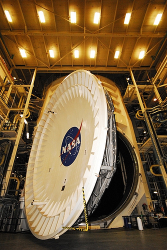
Image by James Webb Space Telescope
NASA’s "Chamber A" thermal vacuum testing chamber famous for becoming utilized in the course of Apollo missions has now been upgraded and remodeled to accommodate testing the James Webb Space Telescope.
When the next-generation space telescope was getting designed, engineers had to guarantee there was a spot large enough to test it, thinking about it really is as massive as a tennis court. That honor fell upon the famous "Chamber A" in the thermal-vacuum test facility at NASA’s Johnson Space Center in Houston, Texas.
Chamber A is now the biggest high-vacuum, cryogenic-optical test chamber in the globe, and created popular for testing the space capsules for NASA’s Apollo mission, with and without the mission crew. It is 55 feet (16.8 meters) in diameter by 90 feet (27.four meters) tall. The door weighs 40 tons and is opened and closed hydraulically.
For three years, NASA Johnson engineers have been creating and remodeling the chamber interior for the temperature needed to test the Webb. Testing will confirm the telescope and science instrument systems will carry out correctly together in the cold temperatures of space. Additional test support gear involves mass spectrometers, infrared cameras and television cameras so engineers can hold an eye on the Webb while it’s being tested.
"Some of the items we’ve accomplished is upgraded our helium system, our liquid nitrogen method, and air flow management," mentioned Virginia Rivas-Yancy, project manager, Air Flow Management Program at NASA Johnson. Temperatures in Chamber A can now drop farther than ever — down to -439.9 Fahrenheit (-262.1 Celsius or 11 degrees Kelvin) which is 11 degrees above absolute zero.
"The air in the chamber weighs 25 tons, about 12 1/2 Volkswagen Beetles when all the air is removed the mass left inside will be the equivalent of half of a staple," mentioned Ryan Grogan, Webb Telescope Chamber A project engineer at NASA Johnson.
A extremely large clean room is also being ready close to Chamber A exactly where the observatory will be prepped for testing. The test itself will take 90 days. The very first 30 days will consist of cooling the chamber down. The next couple of weeks will incorporate tests on the Webb’s operating systems, and the remainder of the time will be spent warming up the chamber to space temperature.
Test articles are usually inserted into the chamber by means of a precision mobile crane, but the Webb is so big, it will be folded up and wheeled in.
Credit: NASA Johnson
Study more: www.nasa.gov/mission_pages/webb/news/chamber-a.html