Some cool metal components china pictures:
Steven F. Udvar-Hazy Center: View down onto SR-71 Blackbird & Boeing P-26A Peashooter
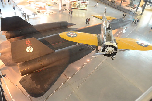
Image by Chris Devers
See much more images of this, and the Wikipedia post.
Specifics, quoting from Smithsonian National Air and Space Museum | Boeing P-26A Peashooter:
The Boeing P-26A of the mid-to-late 1930s introduced the idea of the higher-functionality, all-metal monoplane fighter design and style, which would grow to be common during World War II. A radical departure from wood-and-fabric biplanes, the Peashooter nonetheless retained an open cockpit, fixed landing gear, and external wing bracing.
Most P-26As stationed overseas were at some point sold to the Philippines or assigned to the Panama Canal Department Air Force, a branch of the U.S. Army Air Corps. Several went to China and a single to Spain. This a single was based at Selfridge Field in Michigan and Fairfield Air Depot in Ohio amongst its acceptance by the U.S. Army Air Corps in 1934 and its transfer to the Canal Zone in 1938. It was offered to Guatemala in 1942 and flew in the Guatemalan air force till 1954. Guatemala donated it to the Smithsonian in 1957.
Gift of the Guatemalan Air Force, Republic of Guatemala
Manufacturer:
Boeing Aircraft Co.
Date:
1934
Nation of Origin:
United States of America
Dimensions:
Wingspan: 8.5 m (27 ft 11 in)
Length:7.three m (23 ft 11 in)
Height:3.1 m (ten ft two in)
Weight, empty:996 kg (two,196 lb)
Weight, gross:1,334 kg (2,935 lb)
Best speed:377 km/h (234 mph)
Engine:Pratt & Whitney R-1340-27, 600 hp
Armament:two .30 cal. M2 Browning aircraft machine guns
• • •
Quoting from Boeing History | P-26 "Peashooter" Fighter:
The all-metal, single-wing P-26, popularly identified as the "Peashooter," was an totally new design and style for Boeing, and its structure drew heavily on the Monomail. The Peashooter’s wings were braced with wire, rather than with the rigid struts employed on other airplanes, so the airplane was lighter and had significantly less drag. Its initial high landing speeds had been lowered by the addition of wing flaps in the production models.
Due to the fact the P-26 flew 27 mph faster and outclimbed biplane fighters, the Army ordered 136 production-model Peashooters. Acclaimed by pilots for its speed and maneuverability, the small but feisty P-26 formed the core of pursuit squadrons all through the United States.
Twelve export versions, 11 for China and 1 for Spain, had been built. 1 of a group of P-26s, turned more than to the Philippine Army late in 1941, was among the very first Allied fighters to down a Japanese airplane in Globe War II.
Funds to purchase the export version of the Peashooter were partly raised by Chinese Americans. Contribution boxes have been placed on the counters of Chinese restaurants.
Specifications
• Very first flight: March 20, 1932
• Model number: 248/266
• Classification: Fighter
• Span: 28 feet
• Length: 23 feet 7 inches
• Gross weight: two,995 pounds
• Best speed: 234 mph
• Cruising speed: 200 mph
• Range: 635 miles
• Ceiling: 27,400 feet
• Power: 600-horsepower P&W Wasp engine
• Accommodation: 1 pilot
• Armament: 2 machine guns, 200-pound bomb load
• • • • •
See a lot more pictures of this, and the Wikipedia report.
Particulars, quoting from Smithsonian National Air and Space Museum | Lockheed SR-71 Blackbird:
No reconnaissance aircraft in history has operated globally in more hostile airspace or with such full impunity than the SR-71, the world’s fastest jet-propelled aircraft. The Blackbird’s performance and operational achievements placed it at the pinnacle of aviation technologies developments for the duration of the Cold War.
This Blackbird accrued about 2,800 hours of flight time during 24 years of active service with the U.S. Air Force. On its final flight, March six, 1990, Lt. Col. Ed Yielding and Lt. Col. Joseph Vida set a speed record by flying from Los Angeles to Washington, D.C., in 1 hour, four minutes, and 20 seconds, averaging 3,418 kilometers (2,124 miles) per hour. At the flight’s conclusion, they landed at Washington-Dulles International Airport and turned the airplane over to the Smithsonian.
Transferred from the United States Air Force.
Manufacturer:
Lockheed Aircraft Corporation
Designer:
Clarence L. "Kelly" Johnson
Date:
1964
Country of Origin:
United States of America
Dimensions:
All round: 18ft 5 15/16in. x 55ft 7in. x 107ft 5in., 169998.5lb. (5.638m x 16.942m x 32.741m, 77110.8kg)
Other: 18ft five 15/16in. x 107ft 5in. x 55ft 7in. (5.638m x 32.741m x 16.942m)
Materials:
Titanium
Physical Description:
Twin-engine, two-seat, supersonic strategic reconnaissance aircraft airframe constructed largley of titanium and its alloys vertical tail fins are constructed of a composite (laminated plastic-type material) to minimize radar cross-section Pratt and Whitney J58 (JT11D-20B) turbojet engines function large inlet shock cones.
Extended Description:
No reconnaissance aircraft in history has operated in more hostile airspace or with such full impunity than the SR-71 Blackbird. It is the fastest aircraft propelled by air-breathing engines. The Blackbird’s overall performance and operational achievements placed it at the pinnacle of aviation technology developments in the course of the Cold War. The airplane was conceived when tensions with communist Eastern Europe reached levels approaching a complete-blown crisis in the mid-1950s. U.S. military commanders desperately required precise assessments of Soviet worldwide military deployments, especially near the Iron Curtain. Lockheed Aircraft Corporation’s subsonic U-two (see NASM collection) reconnaissance aircraft was an able platform but the U. S. Air Force recognized that this relatively slow aircraft was already vulnerable to Soviet interceptors. They also understood that the fast development of surface-to-air missile systems could place U-2 pilots at grave threat. The danger proved reality when a U-two was shot down by a surface to air missile over the Soviet Union in 1960.
Lockheed’s 1st proposal for a new high speed, higher altitude, reconnaissance aircraft, to be capable of avoiding interceptors and missiles, centered on a design propelled by liquid hydrogen. This proved to be impracticable since of considerable fuel consumption. Lockheed then reconfigured the design for traditional fuels. This was feasible and the Central Intelligence Agency (CIA), already flying the Lockheed U-2, issued a production contract for an aircraft designated the A-12. Lockheed’s clandestine ‘Skunk Works’ division (headed by the gifted design and style engineer Clarence L. "Kelly" Johnson) developed the A-12 to cruise at Mach 3.two and fly properly above 18,288 m (60,000 feet). To meet these difficult requirements, Lockheed engineers overcame numerous daunting technical challenges. Flying much more than three instances the speed of sound generates 316° C (600° F) temperatures on external aircraft surfaces, which are sufficient to melt traditional aluminum airframes. The design team chose to make the jet’s external skin of titanium alloy to which shielded the internal aluminum airframe. Two standard, but extremely effective, afterburning turbine engines propelled this exceptional aircraft. These energy plants had to operate across a massive speed envelope in flight, from a takeoff speed of 334 kph (207 mph) to far more than three,540 kph (two,200 mph). To prevent supersonic shock waves from moving inside the engine intake causing flameouts, Johnson’s group had to style a complicated air intake and bypass method for the engines.
Skunk Operates engineers also optimized the A-12 cross-section style to exhibit a low radar profile. Lockheed hoped to obtain this by cautiously shaping the airframe to reflect as little transmitted radar energy (radio waves) as achievable, and by application of unique paint made to absorb, rather than reflect, these waves. This treatment became one of the first applications of stealth technologies, but it in no way totally met the style ambitions.
Test pilot Lou Schalk flew the single-seat A-12 on April 24, 1962, right after he became airborne accidentally in the course of higher-speed taxi trials. The airplane showed wonderful guarantee but it needed considerable technical refinement ahead of the CIA could fly the very first operational sortie on May possibly 31, 1967 – a surveillance flight more than North Vietnam. A-12s, flown by CIA pilots, operated as part of the Air Force’s 1129th Particular Activities Squadron under the "Oxcart" system. While Lockheed continued to refine the A-12, the U. S. Air Force ordered an interceptor version of the aircraft designated the YF-12A. The Skunk Functions, nevertheless, proposed a "specific mission" version configured to conduct post-nuclear strike reconnaissance. This program evolved into the USAF’s familiar SR-71.
Lockheed constructed fifteen A-12s, which includes a unique two-seat trainer version. Two A-12s have been modified to carry a specific reconnaissance drone, designated D-21. The modified A-12s have been redesignated M-21s. These had been created to take off with the D-21 drone, powered by a Marquart ramjet engine mounted on a pylon between the rudders. The M-21 then hauled the drone aloft and launched it at speeds higher adequate to ignite the drone’s ramjet motor. Lockheed also constructed 3 YF-12As but this variety in no way went into production. Two of the YF-12As crashed throughout testing. Only one particular survives and is on display at the USAF Museum in Dayton, Ohio. The aft section of a single of the "written off" YF-12As which was later employed along with an SR-71A static test airframe to manufacture the sole SR-71C trainer. One SR-71 was lent to NASA and designated YF-12C. Including the SR-71C and two SR-71B pilot trainers, Lockheed constructed thirty-two Blackbirds. The very first SR-71 flew on December 22, 1964. Since of intense operational expenses, military strategists decided that the far more capable USAF SR-71s should replace the CIA’s A-12s. These have been retired in 1968 after only one year of operational missions, mainly over southeast Asia. The Air Force’s 1st Strategic Reconnaissance Squadron (element of the 9th Strategic Reconnaissance Wing) took over the missions, flying the SR-71 starting in the spring of 1968.
After the Air Force began to operate the SR-71, it acquired the official name Blackbird– for the unique black paint that covered the airplane. This paint was formulated to absorb radar signals, to radiate some of the tremendous airframe heat generated by air friction, and to camouflage the aircraft against the dark sky at high altitudes.
Expertise gained from the A-12 system convinced the Air Force that flying the SR-71 safely essential two crew members, a pilot and a Reconnaissance Systems Officer (RSO). The RSO operated with the wide array of monitoring and defensive systems installed on the airplane. This gear included a sophisticated Electronic Counter Measures (ECM) technique that could jam most acquisition and targeting radar. In addition to an array of advanced, high-resolution cameras, the aircraft could also carry equipment made to record the strength, frequency, and wavelength of signals emitted by communications and sensor devices such as radar. The SR-71 was created to fly deep into hostile territory, avoiding interception with its tremendous speed and high altitude. It could operate safely at a maximum speed of Mach three.3 at an altitude much more than sixteen miles, or 25,908 m (85,000 ft), above the earth. The crew had to wear stress suits related to these worn by astronauts. These suits had been required to safeguard the crew in the event of sudden cabin pressure loss whilst at operating altitudes.
To climb and cruise at supersonic speeds, the Blackbird’s Pratt & Whitney J-58 engines have been made to operate continuously in afterburner. Although this would seem to dictate higher fuel flows, the Blackbird actually achieved its ideal "gas mileage," in terms of air nautical miles per pound of fuel burned, throughout the Mach 3+ cruise. A common Blackbird reconnaissance flight may require several aerial refueling operations from an airborne tanker. Every time the SR-71 refueled, the crew had to descend to the tanker’s altitude, usually about six,000 m to 9,000 m (20,000 to 30,000 ft), and slow the airplane to subsonic speeds. As velocity decreased, so did frictional heat. This cooling effect caused the aircraft’s skin panels to shrink considerably, and these covering the fuel tanks contracted so a lot that fuel leaked, forming a distinctive vapor trail as the tanker topped off the Blackbird. As soon as the tanks had been filled, the jet’s crew disconnected from the tanker, relit the afterburners, and once more climbed to higher altitude.
Air Force pilots flew the SR-71 from Kadena AB, Japan, throughout its operational profession but other bases hosted Blackbird operations, too. The 9th SRW occasionally deployed from Beale AFB, California, to other places to carryout operational missions. Cuban missions had been flown directly from Beale. The SR-71 did not begin to operate in Europe till 1974, and then only temporarily. In 1982, when the U.S. Air Force primarily based two aircraft at Royal Air Force Base Mildenhall to fly monitoring mission in Eastern Europe.
When the SR-71 became operational, orbiting reconnaissance satellites had currently replaced manned aircraft to gather intelligence from websites deep inside Soviet territory. Satellites could not cover every geopolitical hotspot so the Blackbird remained a vital tool for global intelligence gathering. On several occasions, pilots and RSOs flying the SR-71 supplied details that proved essential in formulating productive U. S. foreign policy. Blackbird crews supplied critical intelligence about the 1973 Yom Kippur War, the Israeli invasion of Lebanon and its aftermath, and pre- and post-strike imagery of the 1986 raid carried out by American air forces on Libya. In 1987, Kadena-primarily based SR-71 crews flew a quantity of missions more than the Persian Gulf, revealing Iranian Silkworm missile batteries that threatened commercial shipping and American escort vessels.
As the performance of space-primarily based surveillance systems grew, along with the effectiveness of ground-based air defense networks, the Air Force began to shed enthusiasm for the costly system and the 9th SRW ceased SR-71 operations in January 1990. In spite of protests by military leaders, Congress revived the plan in 1995. Continued wrangling more than operating budgets, even so, quickly led to final termination. The National Aeronautics and Space Administration retained two SR-71As and the a single SR-71B for higher-speed research projects and flew these airplanes until 1999.
On March 6, 1990, the service profession of one Lockheed SR-71A Blackbird ended with a record-setting flight. This special airplane bore Air Force serial quantity 64-17972. Lt. Col. Ed Yeilding and his RSO, Lieutenant Colonel Joseph Vida, flew this aircraft from Los Angeles to Washington D.C. in 1 hour, four minutes, and 20 seconds, averaging a speed of three,418 kph (two,124 mph). At the conclusion of the flight, ‘972 landed at Dulles International Airport and taxied into the custody of the Smithsonian’s National Air and Space Museum. At that time, Lt. Col. Vida had logged 1,392.7 hours of flight time in Blackbirds, more than that of any other crewman.
This particular SR-71 was also flown by Tom Alison, a former National Air and Space Museum’s Chief of Collections Management. Flying with Detachment 1 at Kadena Air Force Base, Okinawa, Alison logged more than a dozen ‘972 operational sorties. The aircraft spent twenty-four years in active Air Force service and accrued a total of 2,801.1 hours of flight time.
Wingspan: 55’7"
Length: 107’5"
Height: 18’6"
Weight: 170,000 Lbs
Reference and Further Reading:
Crickmore, Paul F. Lockheed SR-71: The Secret Missions Exposed. Oxford: Osprey Publishing, 1996.
Francillon, Rene J. Lockheed Aircraft Given that 1913. Annapolis, Md.: Naval Institute Press, 1987.
Johnson, Clarence L. Kelly: A lot more Than My Share of It All. Washington D.C.: Smithsonian Institution Press, 1985.
Miller, Jay. Lockheed Martin’s Skunk Operates. Leicester, U.K.: Midland Counties Publishing Ltd., 1995.
Lockheed SR-71 Blackbird curatorial file, Aeronautics Division, National Air and Space Museum.
DAD, 11-11-01


")

")


