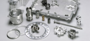
Chamber

The principle reason for the plan of the argon chamber is to permit argon gas into the chamber and let oxygen out. It ought not permit oxygen to go into the chamber and break out argon.

The chamber’s top cover should fit to the CNC axle and laser center point, and furthermore support the temperature of the laser’ ‘s working climate. The calculated plan of the chamber should be created.

The plan prerequisites of the chamber configuration are summed up by oem rapid plastic prototype factory. This cycle recognizes the basic plan boundaries.

rapid prototyping service china shows the argon gas chamber segment configuration dependent on the useful proficiency strategy. This plan cycle brings about the production of the hard top arch, the customization of the plastic sack, the acquisition of elastic and cement sealant, and a heat proof covering.

For the assessment of different ideas, the computerized rationale approach was utilized as appeared in Tables 7.16 and 7.17. Appraisals delivered by the advanced rationale approach are utilized to produce the last arch idea as appeared in Figure 7.54. The format of the vault cover in the last chamber as appeared in Figure 7.55.

In this plan, just the vault is distinguished as the basic resistance highlight. The openings in the vault must fit in the axle and laser center point. The accompanying two stages were thought of:

(a) Fitting with shaft and laser center point: In request to fit the vault with axle and laser center point, for the components of a 5.157 in. measurement opening to fit in the axle and a 4 in. breadth opening to fit in the laser center point as appeared in rapid prototype services, a Class 3 free fit (close sliding fit) was chosen from the ANSI fit standard diagram. This dodges spillage, however on the off chance that there is any hole between the opening and shaft or laser center, an elastic gasket can be applied between particular holes.

(b) When the measurement is dependent upon a predetermined get together necessity and the cutoff points will result from a figuring.

To fit the vault easily into the shaft and laser center, oppositeness resilience to the datum feature”A”as appeared in the figure is basic. The divider thickness between the left-half of the opening and surface,”C”was not known, and in this way should be found by utilizing resilience chain examination as appeared in cnc precision machining factory. The outcome is appeared in china custom design prototyping manufacturers.

To check the basic resiliences and measurements of the CAD model, an engaged model made of cardboard as appeared in cnc high precision machining parts factory for the hard top vault was created. The figure shows the model introduced on the CNC factory to check for fit with the CNC axle and the laser center point. It was discovered to be useful to utilize an engaged model to approve the basic components of the vault before establishment as more subtleties were found to help in the strategy in introducing the arch.

This article is from https://www.precisiontype.com
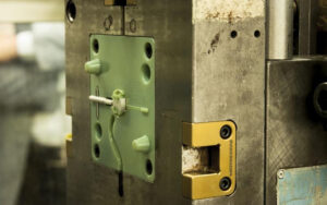
Rapid Prototype: Mask-based Process

The significant preferred position of RP measures is that any mathematical shape can be made with for all intents and purposes no impediment. In any case, as most RP measures, fluid cycles likewise have measure constraints. For example, leaves behind encased and empty structures are issues as the fluid might be caught inside the encased body during building. Except if the fluid can be depleted during the cycle or some way or another tidied up after the assemble, it stays a cycle constraint. The territories of uses are confined because of given material properties. A portrayal of a cover based cycle is SGC,a measure that was designed and created by Cubital Inc. of Israel. The schematics of a cover based cycle are appeared in custom precision cnc machining plastic parts china. The essential material utilized for this cycle is pitch and the auxiliary material utilized is wax. It deals with a standard like the past stereolithography measure, yet for this situation, an entire layer is delivered at a time. A veil based cycle dissects a CAD record and delivers the item as a heap of cuts. The picture of the working cut is”printed” on a glass photomask utilizing an electrostatic cycle like laser printing. To ilustrate further, as appeared in china oem rapid plastic prototype manufacturers, this is a two cycle measure having a veil age cycle and a layer creation cycle. It takes around 2 min to finish all tasks to make a layer: 1. Shower a photosensitive gum on the stage (see Figure 6.50a): The item under development is given a covering of photopolymer (photosensitive) pitch as it passes the sap utensil station on its way to the introduction cell. 2. Plan photomask (Figure 6. 50b): A cover is created by electrostatically moving the toner in the necessary article cross-sectional picture example to a glass plate at a predefined goal. In this cycle, an electron firearm composes a charge design on the plate that is created with toner. This structures an example, which is a negative picture of the cross-area. The machine will at that point present dark electrostatic toner that holds fast to the particle charged segments of the plate. The straightforward zones reflect definitely the cross-segment of the parts. The glass plate at that point moves to the introduction cell where it is situated over the article under development. 3. Fix designed gum by cnc stainless steel prototype suppliers china: A shade is opened permitting the introduction light to go through the cover and rapidly fix the photopolymer layer in the necessary example. All in all, the photosensitive sap layer is presented to UV light through the photomask, and just this uncovered segment is hardened and the rest of the territory is fluid (Figure 6.50d). Since the light is so extreme the layer is completely restored and no optional relieving activity is essential, just like the case with stereolithography. The glass cover is cleaned of toner and released. Another veil is electrophotographically produced on the plate to rehash the cycle. 4. Vacuum-off fluid pitch (Figure 6.50e): The item moves to the streamlined wiper where any sap that was not solidified is vacuumed off and disposed of (Figure 6.50f).

5. Load up with wax (Figure 6.50g): A flimsy layer of fluid wax is then spread over the whole layer, filling the zones that recently held fluid polymer. The wax, which experiences a cooling cycle, encompasses and bolsters the part. 6. Plant the surface (Figure 6.50h): Once the wax cements, a processing shaper is utilized by china design prototype manufacturers to machine the additional wax from over the degree of the photosensitive sap. The layer is processed to the right thickness and produces a level surface prepared for the following layer.

This article is from https://www.precisiontype.com
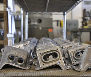
Programming a CMM

During cnc plastic prototyping manufacturers china, machines require high exactness, and in this manner there are some standard techniques to guarantee that the machine is very much qualified before it is utilized. For instance, the CMM is an exact estimating gadget used to confirm measurements to guarantee part quality by cnc high precision machining parts factory. A CMM can be utilized to gauge includes in 2D and 3D, in spite of the fact that 2D highlights can’t be estimated straightforwardly. For instance, a line is a 2D include, and can be characterized by the crossing point of a plane to the reference plane. While a plane is a 3D include, a line can be in a roundabout way characterized by characterizing two planes utilizing a CMM. Most parts are comprised of basic mathematical components, for example, planes, edges, chambers, circles, and cones, made by machining or shaping in cnc precision machining factory. Separation, balance, crossing point, edge, and projection can’t be estimated legitimately, yet should be developed numerically from estimated highlights.

Projection is the multiplication of a workpiece highlight on another element, for instance, anticipating a circle or line on a plane, or a point onto a line. Convergence is the place two existing mathematical components meet and cross one another. For instance, focuses are made by the crossing point of two lines, or of a line and a plane; and lines are made by the convergence of two planes.

The succession for programming a CMM with a test incorporates the accompanying advances:

  1. Home the CMM, and build up a worldwide organize framework.
  2. Qualify the tip, and make up for tip width. Test capability is basic for machine exactness, particularly when the machine is begun every day or when another test is introduced. To qualify the tip, one needs to
  3. Measure a reference circle
  4. Enter the reference circle breadth, real test measurement, and test positions into the PC
  5. The PC figures the successful test distance across and area of the focal point of the test in the estimating volume
  6. Adjust the part, and build up a nearby organize framework on the part. To adjust a section to its CAD model, one needs to adjust
  7. The reference plane
  8. The significant hub
  9. The section zero
  10. Measure the part.

Conventional CMMs commonly have better exactness in precision edm part made in china, however can be restricted in the size and unpredictability of the item to be examined. Versatile CMMs are commonly less precise, however they are compact, with less restriction on the size of an item Measurement frameworks utilizing non-contact innovations, for example, different laser filtering tests or laser global positioning frameworks, can check extremely huge and complex surfaces precisely, yet can be over the top expensive relying upon the sort of framework. Detecting can be ordered into detached detecting and dynamic detecting. Detached detecting is when detecting vitality is just gotten and no vitality is radiated to detect, for instance, sound system vision procedures. Dynamic detecting is when appropriately designed light or some other type of vitality is transmitted as opposed to got once it has connected with the item to digitize, for instance, CT (modernized tomography) and MRI (attractive reverberation imaging).

This article is from https://www.precisiontype.com