A handful of good machining engineering images I discovered:
Image from page 517 of “Railway mechanical engineer” (1916)
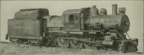
Image by Web Archive Book Images
Identifier: railwaymechanica93newy
Title: Railway mechanical engineer
Year: 1916 (1910s)
Authors:
Subjects: Railroad engineering Engineering Railroads Railroad automobiles
Publisher: New York, N.Y. : Simmons-Boardman Pub. Co
Contributing Library: Carnegie Library of Pittsburgh
Digitizing Sponsor: Lyrasis Members and Sloan Foundation
View Book Page: Book Viewer
About This Book: Catalog Entry
View All Pictures: All Pictures From Book
Click right here to view book on the web to see this illustration in context in a browseable on-line version of this book.
Text Appearing Prior to Image:
en secured to the end of the open exhaust standand extended a number of inches up into the petticoat pipe. Thepetticoat pipe itself has been lowered 18 in. so that its lowerend is now practically on a line with the center line of theboiler suitable. This was accomplished to decrease the draft in thefront end, and thereby in the firebox, in order that the airand coal may possibly enter the firebox at a velocity low sufficient topermit ihe coal to be totally consumed ahead of beingdrawn more than the arch, as a result preventing the accumulation ofslag on the flue sheet. The pulverized coal tank is divided so that pulverizedanthracite sludge might be carried in a single side and bituminouscoal in the other side. Extremely poor grades of coal can beburned in combination with soft coal by so manipulatingthe feed screws as to provide the correct proportions of softcoal and anthracite sludge necessary to maintain a propertemperature. The apparatus for conveying coal from the tender to thelocomotive consists of 4 four-in. feed screws functioning in
Text Appearing Soon after Image:
Lehigh Valley Locomotive Equipped with Pulverized Fuel Burning ApparaUib which engages the teeth in the rack on the lied. The tail-stock spindle is moved by a bandw-heel which is placed con-venient to the carriage. A huge steady rest is providedwith every machine. The bed is ribbed throughout with box sections and isfitted with a rack down a center rib which engages a pawlon the tailstock, as a result removing the thrust of a reduce from theclamps of the tail: lock direct to the bed of the lathe. Thetotal weight of the machine is 150.000 lb. pairs and driven by a variable speed inclosed marine typetwo-cylinder double acting reciprocating engine. The fanfor blowing the coal into the locomotive firebox is driven bya steam turbine. The turbine fan supplies approximately15 to 20 per cent of the air required for combustion, the restbeing drawn in by the action of the exhaust by means of theopenings in the firebox and in the burner correct. The four feeders operating in pairs avoid the fuel fromarchin
Note About Images
Please note that these images are extracted from scanned page pictures that might have been digitally enhanced for readability – coloration and appearance of these illustrations may possibly not completely resemble the original operate.
Image from web page 102 of “Les raisons des forces mouuantes auec diuerses machines tant vtilles que plaisantes aus quelles sont adioints plusieurs desseings de grotes et fontaines” (1615)
Image by World wide web Archive Book Photos
Identifier: gri_c00033125008477123
Title: Les raisons des forces mouuantes auec diuerses machines tant vtilles que plaisantes aus quelles sont adioints plusieurs desseings de grotes et fontaines
Year: 1615 (1610s)
Authors: Caus, Salomon de, d. 1626
Subjects: Mechanical engineering Hydraulic barrel organ Fountains Grottoes (Garden structures)
Publisher: A Francfort, En la boutique de Jan Norton
Contributing Library: Getty Investigation Institute
Digitizing Sponsor: Getty Research Institute
View Book Web page: Book Viewer
About This Book: Catalog Entry
View All Images: All Photos From Book
Click here to view book online to see this illustration in context in a browseable online version of this book.
Text Appearing Just before Image:
A LATKES1LLVST%E ET VERTVEVSE PR[NCI S SE
Text Appearing Right after Image:
Note About Photos
Please note that these images are extracted from scanned page images that may possibly have been digitally enhanced for readability – coloration and appearance of these illustrations might not perfectly resemble the original work.
Image from web page 324 of “Railway and locomotive engineering : a sensible journal of railway motive power and rolling stock” (1901)
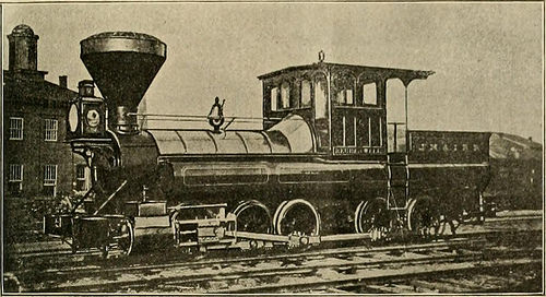
Image by World wide web Archive Book Images
Identifier: railwaylocomotiv19newy
Title: Railway and locomotive engineering : a practical journal of railway motive power and rolling stock
Year: 1901 (1900s)
Authors:
Subjects: Railroads Locomotives
Publisher: New York : A. Sinclair Co
Contributing Library: Carnegie Library of Pittsburgh
Digitizing Sponsor: Lyrasis Members and Sloan Foundation
View Book Page: Book Viewer
About This Book: Catalog Entry
View All Pictures: All Photos From Book
Click here to view book on the internet to see this illustration in context in a browseable on-line version of this book.
Text Appearing Prior to Image:
aggregate railway mileage in the Pro-vince is 1,174 miles. There were 48 newiron bridges constructed in 1905 and iiS othersare beneath construction. The totalamount expended on roadways andbridges was over ,000. July, igo6. RAILWAY AND LOCOMOTIVE ENGINEERING 313 Historic Locomotive.By the courtesy of the PennsylvaniaLines, and specifically as a outcome of theinterest shown by Mr. D. F. Crawford,common superintendent of motive power,Purdue University, at Lafayette, Ind.,has been able to add a machine of morethan passing interest to its collectionof historic locomotives. This most recent ac-quisition, which is the sixth loconintivc versity. This engine, when place to perform,and with plain wheels, performed a serv-ice which had previously involved theuse of gears. It was in reality a most ex-cellent adaptation of the means to anend, the significance of which becomesgieater when it is remembered that itwas place in service in i868. A matter which lends interest to thegiving of this loconiotivc to Purdue Uni-
Text Appearing Soon after Image:
FIG. I. TANK LOCOMOTIVt REUBEN WELLS, FORMEKLV l)N J., M. 6t I. R. R. to take its place in the Purdue museum,is the Reuben Wells, which was builtin 1868 by what was then the Jefferson-ville, Madison & Indianapolis Railway,for use on the Madison incline. Its ap-pearance when new is shown in Fig. i.It was remodeled somewhat not too long ago, therear end of the frame possessing been cutoflf, the number of axles decreased fromfive to four, and a saddle tank placedover the boiler. The engine as it nowappears is shown in Fig. two. This engine has been employed in the im-mediate vicinity of the city of Madison,Ind. Located upon the Ohio river andsurrounded on the east, west and northby hills increasing to a height of more than 400 ft.,Madison was easily accessible from thewater, but the steep hills on all of theroads leading away from the town madeit challenging to distribute merchandise tothe interior. After a extended period of dis-cussion the construction of a railroadwas lastly undertaken. The initial por-tion of th
Note About Images
Please note that these images are extracted from scanned page photos that might have been digitally enhanced for readability – coloration and look of these illustrations may not completely resemble the original operate.