Good China Mechanical Engineering photographs

Good China Mechanical Engineering photographs

Verify out these china mechanical engineering pictures:

Image from web page 615 of “Railway mechanical engineer” (1916)
china mechanical engineering
Image by World wide web Archive Book Pictures
Identifier: railwaymechanica95newy
Title: Railway mechanical engineer
Year: 1916 (1910s)
Authors:
Subjects: Railroad engineering Engineering Railroads Railroad vehicles
Publisher: New York, N.Y. : Simmons-Boardman Pub. Co
Contributing Library: Carnegie Library of Pittsburgh
Digitizing Sponsor: Lyrasis Members and Sloan Foundation

View Book Web page: Book Viewer
About This Book: Catalog Entry
View All Photos: All Photos From Book

Click right here to view book on-line to see this illustration in context in a browseable on the web version of this book.

Text Appearing Ahead of Image:
ct. The operation of this systemlightens the work and tends to make it significantly much more easy and favorablefor the workmen handling material, thereby decreasing laborturnover and increasing the efficiency of unskilled labor.The method is being manufactured and sold by the WhitingCorporation, Harvey, 111. Special Hydraulic Driving Wheel Press THE Hydraulic Press Manufacturing Company, MountGilead, Ohio, designed and constructed the unique hydraulicpress, illustrated, which was not too long ago sold by the Mc-Carter Cooper Company, New York, to the Compagnie Gen-eral De Chemins De Fer &amp Tramways en Chine, Pekin,China. This press is utilized for forcing driving wheels on or off between strain bars is 84 in. and in between ram and resistancehead is 108 in. maximum. This may be decreased to 78 in.by moving the resistance head, which is mounted on wheels.The press is also equipped with a belt-driven energy attach-ment and three plunger pump with each low and high pres-positive plungers. The pump is equipped with hand and pres-

Text Appearing Soon after Image:
Hydraulic Press for Applying Driving Wheels to Crank Axles the crank-axles of locomotives, a special style of press beingnecessary due to the fact of the crank throws. The press will manage wheels 80 in. in diameter and significantly less,becoming capable of exerting a force of 330 tons. The distance certain knock-outs whereby any one particular or all pump cylinders perhaps eliminated from service at will or automatically when themaximum pressure is reached. A little hydraulic cylinderand ram returns the main ram to its beginning position. Railway

Note About Photos
Please note that these pictures are extracted from scanned page photos that may have been digitally enhanced for readability – coloration and appearance of these illustrations may not perfectly resemble the original perform.

Cool Precision Engineering Organizations images

Cool Precision Engineering Organizations images

Verify out these precision engineering businesses images:

1968 Lancia Fulvia Sport 1.three S Zagato
precision engineering companies
Image by Georg Sander
The Lancia Fulvia is an Italian vehicle introduced at the Geneva Motor Show in 1963 by Lancia. It was produced by that organization through 1976. Fulvias are notable for their function in automobile racing history, such as winning the International Rally Championship in 1972. On testing it in 1967, Road &amp Track summed up the Fulvia as &quota precision motorcar, an engineering tour de force&quot.

(Wikipedia)

– – –

Der Lancia Fulvia ist ein Automobil des italienischen Herstellers Lancia. Es wurde von Herbst 1963 bis Ende 1976 gebaut und gilt als Nachfolgemodell des Lancia Appia.

Wie andere nach dem 1950 vorgestellten Aurelia entwickelten Lancia-Modelle war der Fulvia nach einer klassischen Römerstraße, hier der Via Fulvia, benannt. Im Herbst 1972 wurde dieses Technique der Benennung wieder geändert: der unter Fiat-Regie gebaute Nachfolger des Fulvia war der Lancia Beta.

Der Fulvia war als Berlina (Limousine) und als Coupé erhältlich. Außerdem gab es wie bei Lancia üblich ein bei Carrozzeria Zagato entworfenes und in Kleinserie gebautes Fließheckcoupé mit dem traditionellen Namen Sport. Das technische Konzept des Fulvia stammt von Antonio Fessia, die Form wurde von Pietro Castagnero bei Lancia entworfen.

(Wikipedia)

Image from web page 454 of “American engineer and railroad journal” (1893)
precision engineering companies
Image by Net Archive Book Pictures
Identifier: americanengineer78newy
Title: American engineer and railroad journal
Year: 1893 (1890s)
Authors:
Subjects: Railroad engineering Engineering Railroads Railroad automobiles
Publisher: New York : M.N. Forney
Contributing Library: Carnegie Library of Pittsburgh
Digitizing Sponsor: Lyrasis Members and Sloan Foundation

View Book Web page: Book Viewer
About This Book: Catalog Entry
View All Images: All Pictures From Book

Click right here to view book on the internet to see this illustration in context in a browseable on-line version of this book.

Text Appearing Ahead of Image:
machine is created by the Lucas Machine Tool Organization of Cleve-land, and is known as No. 1 Precision boring, drilling and mill-ing machine. They also make a No. 2 machine of the samegeneral design and style, but larger in size and better adapted to theclass of function it would be essential to deal with in a railroad shop. We expect to build a shop or shed with two tracks longenough to hold twenty steel automobiles each and every. Ahead of they are takenin on track No. 1 we will eliminate the scale from the insidewith a pneumatic hammer and the paint and rust from theoutside with a sand blast. Then as they are run in we pro-pose to paint them with a movable spraying machine suspendedabove the cars on a track running the length of the shop, usinga double hose, so that both sides of the cars can be painted atthe very same time. Soon after giving them two coats we will place themon track No. 2 for drying and stenciling.—B. F. Wynn, MasterCar and Locomotive Painters Association. NliMMllKIt, 1904. AMERICAN ENGINEEB AM) UAII.KOAI) JOURNAL. 411

Text Appearing Right after Image:
SS^S ml MHlol BE EQUIPPED WITH OVEBHEAD CRANES AND MOVABLE TELESCOPIC BMOKE JACKS.

Note About Photos
Please note that these images are extracted from scanned web page pictures that could have been digitally enhanced for readability – coloration and look of these illustrations may possibly not perfectly resemble the original function.

Latest Milling Engineering News

Latest Milling Engineering News

Hagen – Freilichtmuseum Hagen – Deutsches Schmiedemuseum
milling engineering
Image by Daniel Mennerich (subsequent stop Hà Nội)
The Hagen Open-air Museum (LWL-Freilichtmuseum Hagen – Westfälisches Landesmuseum für Handwerk und Technik English: &quotLWL Open-air Museum Hagen – Westphalian State Museum for Craft and Technics&quot) is a museum at Hagen in the southeastern Ruhr location, North Rhine-Westphalia, Germany. It was founded, together with the Detmold Open-air Museum, in 1960, and was first opened to the public in the early 1970s. The museum is run by the Landschaftsverband Westfalen-Lippe (LWL, regional authority for Westphalia and Lippe within North Rhine-Westphalia). It lies in the Hagen neighbourhood of Selbecke south of Eilpe in the Mäckingerbach valley.

The open-air museum brings a bit of skilled-trade history into the present, and it requires a hands-on strategy. On its grounds stretching for about 42 ha, not only are urban and rural trades merely &quotdisplayed&quot along with their workshops and tools, but in a lot more than twenty of the almost sixty rebuilt workshops, they are nevertheless practised, and interested guests can, occasionally by themselves, take component in the production.

As early as the 1920s, there were efforts by a group of engineers and historical preservationists to preserve technological monuments for posterity. The initiator, Wilhelm Claas, even suggested the Mäckingerbach valley as a great spot for a museum to that end. The narrow valley was selected, as wind, water and wood had been the three most essential location aspects for business in the 18th and 19th centuries.

In 1960, the Westphalian Open-Air Museum was founded, and thirteen years later, the gates opened to the public. As opposed to most open-air museums, which show daily life on the farm or in the country as it was in days gone by, the Hagen Open-Air Museum puts the history of these activities in Westphalia in the fore. From the late 18th century by way of the early years of the Industrial Revolution to the extremely industrialized society emerging in the early 20th century, the visitor can encounter the development of these trades and the industry in the region.

Crafts and trades demonstrated at the Westphalian Open-Air Museum include ropemaking, smithing, brewing, baking, tanning, printing, milling, papermaking, and a lot far more. A favourite attraction is the triphammer workshop shown in the image above. After the hammer is engaged, a craftsman goes to operate noisily forging a scythe, passing it amongst the hammer and the anvil underneath in a approach known as peening.

The Hagen Westphalian Open-Air Museum is open from March or April until October.

ERP for Project Engineering Companies

ERP for Project Engineering Companies

Buoyed by the quick-expanding economy, Engineering Services and Project Consulting organizations across sub-segments like Electrical, Mechanical, Electronics, Construction, Architectural is experiencing unprecedented business opportunities. Even so, these possibilities could be missed if a business does not have the appropriate systems to accommodate advanced project management, accurate financial reporting, and expanding buyer/vendor demands for true-time data exchanges.

The goal of ERP is to assistance 1 time entry of info at the point exactly where it is designed and to make it available to all the participants inside the organization. The engineering market is a very fragmented industry. It wants to communicate on a huge scale with other related organizations such as material and equipment suppliers, vendors, subcontractors and clients. ERP systems are getting employed by firms to improve responsiveness in relation to customers, strengthen supply chain partnerships, improve organizational flexibility, improve choice creating capabilities and decrease project completion time and decrease charges. These details systems are designed to integrate and partially automate several of the company’s business processes such as human resources, economic management, manufacturing, procurement, construction, operations and maintenance.

These organizations execute a wide range of projects across business verticals which make it essential for them to adopt best practices. The project engineering organizations face challenges related to project and material management. With every new project that is won by project engineering firms, post analysis and requirement scoping, a detailed design and element choice is undertaken. A Bill of materials is then developed which goes to the acquire division wherein it has to be logged in against the specific project. In such a complicated situation there is a major challenge in material management, tracking and preparing. Also since there are various expenses to be incorporated into the project billing, such as material expense, time price of man-hours spent by personnel from multiple departments. The billing process is also fairly complex as invoices need to be raised at any phase of the project.

Crucial Features

Price range and Actual for material, labour, revenue and other costs is essential and require strong material management. The Project Job Costing module of ERP enables organizations to do effective material management, keep inventory costs below manage and streamline material procurement approach.
ERP expense tracking capabilities ensures accurate tracking of different expense elements relating to folks, material and travel. Given that it automatically tracks the project expense throughout its life cycle, it makes it possible for the managers to keep track of project profitability at all occasions.
Tight integration of the Project and Job Costing system with finance and buy functions advantage to evade duplication of entries and guarantees accuracy of information.
Also the automated billing functions in the job price accounting software
Streamlines customer invoicing so that there are no leakages in the billing.

Project Engineering businesses in particular rely on robust processes, supported by specialized technologies, to define scope and handle projects from initial bid to project completion. To handle buyer expectations for projects—including time, supplies, and labor—engineering organizations require to optimize operational processes. A robust ERP answer enables you to streamline processes give all project stakeholders deep visibility into centralized, genuine-time details and fuel collaboration that leads to winning results.

Author on various topics for softwares, saas softwares and cloud computing for SMEs, For more info on ERP please check out ERP Solutions

Related Precision Engineering Companies Articles

Good Precision Parts Engineering photos

Good Precision Parts Engineering photos

Some cool precision components engineering pictures:

Image from web page 196 of “Railway mechanical engineer” (1916)
precision parts engineering
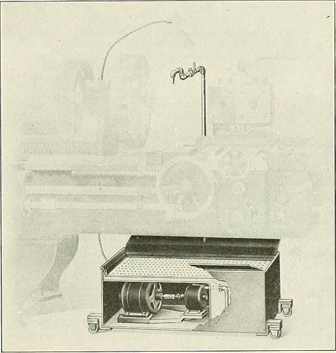
Image by Web Archive Book Pictures
Identifier: railwaymechanica94newy
Title: Railway mechanical engineer
Year: 1916 (1910s)
Authors:
Subjects: Railroad engineering Engineering Railroads Railroad automobiles
Publisher: New York, N.Y. : Simmons-Boardman Pub. Co
Contributing Library: Carnegie Library of Pittsburgh
Digitizing Sponsor: Lyrasis Members and Sloan Foundation

View Book Web page: Book Viewer
About This Book: Catalog Entry
View All Pictures: All Photos From Book

Click here to view book on the web to see this illustration in context in a browseable on-line version of this book.

Text Appearing Before Image:
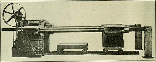
be speedily applied to anymachine tool in the shop. Several machine shop tools arenot equipped with a pan and pump, due to the fact they are usedmostly for functioning on grey iron, but sometimes the ma-chine might be used on malleable iron or steel, in which casea coolant is important for the greatest benefits. In such instances, theportable unit illustrated can be utilized to great advantage.It may also be used on machines currently provided with acoolant program, which for some cause or other is out oforder. In this emergency the transportable method shown can be instantly brought into location and production will notbe interrupted. The Fulllo pump illustrated is a total, self-containedsystem, requiring practically nothing but attaching the motor cord tothe lump socket. The total height from the floor is only14 in., which pennits its being rolled below any ordinarylathe, as shown in the illustration. Provision is produced forattaching further splash boards when essential. Thepump and motor are totally covered, as a result affording

Text Appearing Right after Image:
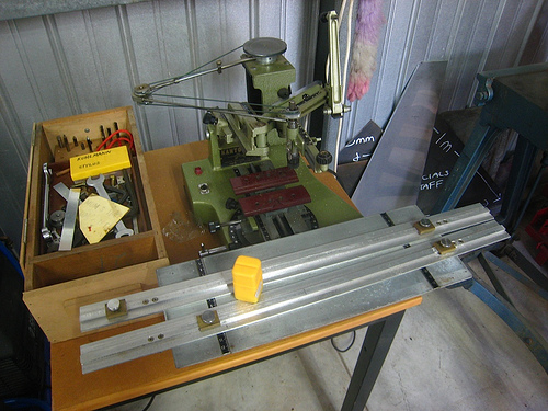
Fulflo Portable Lubricating Unit Utilized with Turret Lathe ample protection from each liquids and dust. The outfitcan be utilized on grinding machines as w-ell as on lathes,milling machines, drill presses, gear cutters, and so forth. Thereis only one particular moving part in the pump namely, the impeller,which has no metal contact, and for that reason cannot wear outquickly. It is packed with metallic packing which willnot reduce the shaft. The bearings are nicely lubricated, andsince the shaft is hardened and ground, extended, continuedservice may be anticipated. MULTI GRADUATED PRECISION GRINDER It has Ijeen tough in the past to machine screw threadsurfaces with the same accuracy obtained in machiningcylindrical, flat or spherical surfaces. On account of thisfact, it has been difficult to make master thread gages and themachine illustrated was created for this goal by thePrecision &amp Thread Grinder Manufacturing Company, Phil-adelphia, Pa. It can be employed in conjunction with anymachine tool and is adaptable to a selection

Note About Pictures
Please note that these photos are extracted from scanned web page pictures that may possibly have been digitally enhanced for readability – coloration and look of these illustrations could not perfectly resemble the original work.

Steven F. Udvar-Hazy Center: North American P-51C, “Excalibur III”, with tails of Concorde & Boeing 707 in background
precision parts engineering
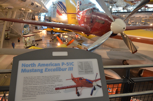
Image by Chris Devers
Quoting Smithsonian National Air and Space Museum | North American P-51C, &quotExcalibur III&quot:

On Could 29, 1951, Capt. Charles F. Blair flew Excalibur III from Norway across the North Pole to Alaska in a record-setting 10½ hours. Making use of a method of meticulously plotted &quotsun lines&quot he created, Blair was in a position to navigate with precision exactly where conventional magnetic compasses usually failed. 4 months earlier, he had flown Excalibur III from New York to London in significantly less than eight hours, breaking the existing mark by over an hour.

Excalibur III very first belonged to famed aviator A. Paul Mantz, who added added fuel tanks for long-distance racing to this normal P-51C fighter. With it Mantz won the 1946 and 1947 Bendix air race and set a transcontinental speed record in 1947 when the airplane was named Blaze of Noon. Blair bought it from Mantz in 1949 and renamed it Excalibur III, following the Sikorsky VS-44 flying boat he flew for American Export Airlines.

Present of Pan American Planet Airways

Manufacturer:
North American Aircraft Firm

Date:
1944

Nation of Origin:
United States of America

Dimensions:
Wingspan: 11.three m (37 ft)
Length: 9.eight m (32 ft three in)
Height: three.9 m (12 ft ten in)
Weight, empty: 4,445 kg (9,800 lb)
Weight, gross: 5,052 kg (11,800 lb)
Leading speed: 700 km/h (435 mph)

Supplies:
Overall: Aluminum

Physical Description:
Single seat, single engine, low wing monoplane, Planet War II fighter modified for racing.

• • • • •

Quoting Smithsonian National Air and Space Museum | Boeing 367-80 Jet Transport:

On July 15, 1954, a graceful, swept-winged aircraft, bedecked in brown and yellow paint and powered by four revolutionary new engines 1st took to the sky above Seattle. Built by the Boeing Aircraft Company, the 367-80, greater recognized as the Dash 80, would come to revolutionize industrial air transportation when its created version entered service as the renowned Boeing 707, America’s 1st jet airliner.

In the early 1950s, Boeing had begun to study the possibility of creating a jet-powered military transport and tanker to complement the new generation of Boeing jet bombers entering service with the U.S. Air Force. When the Air Force showed no interest, Boeing invested million of its personal capital to build a prototype jet transport in a daring gamble that the airlines and the Air Force would buy it after the aircraft had flown and verified itself. As Boeing had accomplished with the B-17, it risked the company on 1 roll of the dice and won.

Boeing engineers had initially primarily based the jet transport on research of improved designs of the Model 367, better identified to the public as the C-97 piston-engined transport and aerial tanker. By the time Boeing progressed to the 80th iteration, the design and style bore no resemblance to the C-97 but, for security reasons, Boeing decided to let the jet project be identified as the 367-80.

Operate proceeded swiftly right after the formal start off of the project on May possibly 20, 1952. The 367-80 mated a huge cabin primarily based on the dimensions of the C-97 with the 35-degree swept-wing design primarily based on the wings of the B-47 and B-52 but considerably stiffer and incorporating a pronounced dihedral. The wings had been mounted low on the fuselage and incorporated higher-speed and low-speed ailerons as effectively as a sophisticated flap and spoiler technique. 4 Pratt &amp Whitney JT3 turbojet engines, every producing 10,000 pounds of thrust, have been mounted on struts beneath the wings.

Upon the Dash 80’s initial flight on July 15, 1954, (the 34th anniversary of the founding of the Boeing Firm) Boeing clearly had a winner. Flying 100 miles per hour quicker than the de Havilland Comet and considerably bigger, the new Boeing had a maximum variety of much more than 3,500 miles. As hoped, the Air Force bought 29 examples of the design as a tanker/transport after they convinced Boeing to widen the design by 12 inches. Satisfied, the Air Force designated it the KC-135A. A total of 732 KC-135s were constructed.

Quickly Boeing turned its attention to promoting the airline industry on this new jet transport. Clearly the sector was impressed with the capabilities of the prototype 707 but never ever far more so than at the Gold Cup hydroplane races held on Lake Washington in Seattle, in August 1955. In the course of the festivities surrounding this occasion, Boeing had gathered a lot of airline representatives to appreciate the competitors and witness a fly past of the new Dash 80. To the audience’s intense delight and Boeing’s profound shock, test pilot Alvin &quotTex&quot Johnston barrel-rolled the Dash 80 over the lake in full view of thousands of astonished spectators. Johnston vividly displayed the superior strength and overall performance of this new jet, readily convincing the airline sector to get this new airliner.

In searching for a market, Boeing discovered a prepared consumer in Pan American Airway’s president Juan Trippe. Trippe had been spending a lot of his time looking for a appropriate jet airliner to allow his pioneering business to sustain its leadership in international air travel. Working with Boeing, Trippe overcame Boeing’s resistance to widening the Dash-80 design and style, now recognized as the 707, to seat six passengers in every single seat row rather than 5. Trippe did so by placing an order with Boeing for 20 707s but also ordering 25 of Douglas’s competing DC-8, which had but to fly but could accommodate six-abreast seating. At Pan Am’s insistence, the 707 was produced four inches wider than the Dash 80 so that it could carry 160 passengers six-abreast. The wider fuselage created for the 707 became the regular style for all of Boeing’s subsequent narrow-body airliners.

Though the British de Havilland D.H. 106 Comet and the Soviet Tupolev Tu-104 entered service earlier, the Boeing 707 and Douglas DC-8 were larger, more quickly, had higher range, and had been far more lucrative to fly. In October 1958 Pan American ushered the jet age into the United States when it opened international service with the Boeing 707 in October 1958. National Airlines inaugurated domestic jet service two months later using a 707-120 borrowed from Pan Am. American Airlines flew the initial domestic 707 jet service with its personal aircraft in January 1959. American set a new speed mark when it opened the first often-scheduled transcontinental jet service in 1959. Subsequent nonstop flights amongst New York and San Francisco took only 5 hours – three hours much less than by the piston-engine DC-7. The a single-way fare, such as a surcharge for jet service, was five.50, or 1 round trip. The flight was nearly 40 percent more rapidly and virtually 25 percent more affordable than flying by piston-engine airliners. The consequent surge of targeted traffic demand was substantial.

The 707 was originally designed for transcontinental or a single-cease transatlantic variety. But modified with further fuel tanks and more efficient turbofan engines, the 707-300 Intercontinental series aircraft could fly nonstop across the Atlantic with full payload below any situations. Boeing constructed 855 707s, of which 725 were bought by airlines worldwide.

Having launched the Boeing Company into the commercial jet age, the Dash 80 soldiered on as a highly effective experimental aircraft. Till its retirement in 1972, the Dash 80 tested numerous advanced systems, many of which have been incorporated into later generations of jet transports. At one point, the Dash 80 carried three distinct engine kinds in its four nacelles. Serving as a test bed for the new 727, the Dash 80 was briefly equipped with a fifth engine mounted on the rear fuselage. Engineers also modified the wing in planform and contour to study the effects of diverse airfoil shapes. Many flap configurations were also fitted which includes a highly sophisticated method of &quotblown&quot flaps which redirected engine exhaust over the flaps to increase lift at low speeds. Fin height and horizontal stabilizer width was later improved and at one particular point, a special a number of wheel low stress landing gear was fitted to test the feasibility of operating future heavy military transports from unprepared landing fields.

After a extended and distinguished profession, the Boeing 367-80 was finally retired and donated to the Smithsonian in 1972. At present, the aircraft is installated at the National Air and Space Museum’s new facility at Washington Dulles International Airport.

Present of the Boeing Company

Manufacturer:
Boeing Aircraft Co.

Date:
1954

Nation of Origin:
United States of America

Dimensions:
Height 19′ 2&quot: Length 73′ ten&quot: Wing Span 129′ eight&quot: Weight 33,279 lbs.

Physical Description:
Prototype Boeing 707 yellow and brown.

• • • • •

Quoting Smithsonian National Air and Space Museum | Concorde, Fox Alpha, Air France:

The initial supersonic airliner to enter service, the Concorde flew thousands of passengers across the Atlantic at twice the speed of sound for more than 25 years. Developed and built by Aérospatiale of France and the British Aviation Corporation, the graceful Concorde was a stunning technological achievement that could not overcome serious financial troubles.

In 1976 Air France and British Airways jointly inaugurated Concorde service to destinations about the globe. Carrying up to 100 passengers in excellent comfort, the Concorde catered to 1st class passengers for whom speed was vital. It could cross the Atlantic in fewer than four hours – half the time of a traditional jet airliner. Even so its higher operating charges resulted in really higher fares that restricted the number of passengers who could afford to fly it. These problems and a shrinking industry at some point forced the reduction of service till all Concordes were retired in 2003.

In 1989, Air France signed a letter of agreement to donate a Concorde to the National Air and Space Museum upon the aircraft’s retirement. On June 12, 2003, Air France honored that agreement, donating Concorde F-BVFA to the Museum upon the completion of its last flight. This aircraft was the 1st Air France Concorde to open service to Rio de Janeiro, Washington, D.C., and New York and had flown 17,824 hours.

Present of Air France.

Manufacturer:
Societe Nationale Industrielle Aerospatiale
British Aircraft Corporation

Dimensions:
Wingspan: 25.56 m (83 ft 10 in)
Length: 61.66 m (202 ft 3 in)
Height: 11.3 m (37 ft 1 in)
Weight, empty: 79,265 kg (174,750 lb)
Weight, gross: 181,435 kg (400,000 lb)
Leading speed: 2,179 km/h (1350 mph)
Engine: 4 Rolls-Royce/SNECMA Olympus 593 Mk 602, 17,259 kg (38,050 lb) thrust every
Manufacturer: Société Nationale Industrielle Aérospatiale, Paris, France, and British Aircraft Corporation, London, United Kingdom

Physical Description:
Aircaft Serial Number: 205. Such as four (4) engines, bearing respectively the serial quantity: CBE066, CBE062, CBE086 and CBE085.
Also included, aircraft plaque: &quotAIR FRANCE Lorsque viendra le jour d’exposer Concorde dans un musee, la Smithsonian Institution a dores et deja choisi, pour le Musee de l’Air et de l’Espace de Washington, un appariel portant le couleurs d’Air France.&quot

Nice Machining Engineering photographs

Nice Machining Engineering photographs

Verify out these machining engineering photos:

Image from web page 492 of “Railway and locomotive engineering : a sensible journal of railway motive energy and rolling stock” (1901)
machining engineering
Image by Internet Archive Book Photos
Identifier: railwaylocomotiv18newy
Title: Railway and locomotive engineering : a practical journal of railway motive power and rolling stock
Year: 1901 (1900s)
Authors:
Subjects: Railroads Locomotives
Publisher: New York : A. Sinclair Co
Contributing Library: Carnegie Library of Pittsburgh
Digitizing Sponsor: Lyrasis Members and Sloan Foundation

View Book Web page: Book Viewer
About This Book: Catalog Entry
View All Pictures: All Pictures From Book

Click here to view book on the web to see this illustration in context in a browseable on the internet version of this book.

Text Appearing Ahead of Image:
Computer is in a neat folding, leather-cov-ered case. A single side provides formula and dircctionifor use. The other side has a graduated circleupon which turns a graduated card disc. Ctt.r b« Adjusted In a. Momentto Give Result With no Calculation THIS OFFICEPrice. .00 Eetch Model Locomotives and Castingfs Better than ever! Most current N. Y. Cen.Common. High Saddles —Bg Drivers—4 sizes Anything further nice. 4c. instamps for catalog. . S.P. O. Box 2«8. CAn Bl LL. Monllcello, N. Y October, 1905. RAILWAY AND LOCOMOTIVE ENGINEERING 481 AIR BRAKE MODELS For Self Instruction. WITH CHART. AIK CHAMBHKS CI)I.ORi:il.AI.I, Parts NIIMHKRKI). Improved Portable Boring, Milling andDrilling Machine. Tlic Espcii-Lucas Maclunc Business,of Philadelpliia, has just placed on themarket many improved portable ma- lls range of speeds ctnbraccs every re-(liiisite from the smallest drill to thelargest cutter. The materials are all ofthe extremely ideal, the spindle becoming ofhammered crucible steel 4 ins. in diam-

Text Appearing Right after Image:
SectlonalModel WestinghouseQuick ActionTriple Valve.Cut 14 actual size. Cost.50 post°paJcL Manufactured by W. VAN NAME 360 Evergreen Ave., BROOKLYN, N. Y. imEljmoN SWITCH &ampSIGNAL CO. Consulting and ManufacturingSignal Engineers Automatic Block Signals—Electricand Electro-Pneumatic Interlocking—Electric, Electro-Pneu-matic and Mechanical Electric Train Staff Apparatus General OFFICES AND Operates ATSWISSVALE, PA. DISTRICT OFFICES: New York: 143 Liberty StreetChlca]o: nitnadnock Block5t. Louis : Frisco Developing Patents. QEO. P. WHITTLESEY McQILL BUILOINQ WASMINQTON, D. C. Terms Affordable. Pamphlet Sent

Note About Pictures
Please note that these pictures are extracted from scanned web page photos that may have been digitally enhanced for readability – coloration and appearance of these illustrations may not perfectly resemble the original operate.

Engraving machine
machining engineering
Image by brotherlywalks

Nice Higher Precision Engineering images

Nice Higher Precision Engineering images

Check out these higher precision engineering photos:

AF Memorial_Light the Night
high precision engineering
Image by catface3
Air Force Memorial, Washington, DC, on a hill overlooking the Pentagon. Subsequent to Arlington National Cemetery and to Ft Myer, Virginia, exactly where the Wright brothers 1st demonstrated their Flyer for the Army.

en.wikipedia.org/wiki/United_States_Air_Force_Memorial

&quotThe Memorial itself is 270 feet (82 m) higher and appears to be soaring its array of stainless steel arcs against the sky evokes the image of &quotcontrails of the Air Force Thunderbirds as they peel back in a precision ‘bomb burst’ maneuver.&quot Only three of the 4 contrails are depicted, as the absent fourth evokes the missing man formation traditionally utilised at Air Force funeral fly-overs.&quot
&quotThe spire structure consists of stainless steel plates with high-strength concrete filling the lower 2/3rds of every single spire. The upper third is hollow stainless steel.[six] At the transition amongst concrete and hollow steel portions, dampers are offered to dissipate wind sway power and eradicate the threat of aerodynamic instability. Every single damper consists of a lead ball weighing about a ton each and every, allowed to roll inside a steel box. The structural design of the memorial was completed by engineering.&quot

Cool Mechanical Engineering China images

Cool Mechanical Engineering China images

Some cool mechanical engineering china photos:

Image from web page 421 of “Morton memorial a history of the Stevens institute of technologies, with biographies of the trustees, faculty, and alumni, and a record of the achievements of the Stevens family of engineers” (1905)
mechanical engineering china
Image by Web Archive Book Images
Identifier: mortonmemorialhi00furm
Title: Morton memorial a history of the Stevens institute of technologies, with biographies of the trustees, faculty, and alumni, and a record of the achievements of the Stevens household of engineers
Year: 1905 (1900s)
Authors: Furman, Franklin De Ronde, 1870- ed
Subjects: Stevens family members Morton, Henry, 1836-1902 Stevens Institute of Technologies
Publisher: Hoboken, N.J., Stevens institute of technology
Contributing Library: The Library of Congress
Digitizing Sponsor: The Library of Congress

View Book Page: Book Viewer
About This Book: Catalog Entry
View All Pictures: All Images From Book

Click right here to view book on-line to see this illustration in context in a browseable online version of this book.

Text Appearing Ahead of Image:
1899.He has two youngsters, William Arnaud andMadeleine Arnaud Fox. Fraentzel, Frederick C. (M.E., 83), wasborn in Newark, N. J., June 4, 1862. He wasassistant in the department of maintenanceof ways of the Pennsylvania Railroad, JerseyCity, 1883 in the shops of the Pittsburg,Chicago, &amp St. Louis Railroad, Logansport.Ind., 1883-84 and first assistant engineerwith the Celluloid Manufacturing Co., New-ark, N. J., 1884-85. He has been a memberof the firm of Campbell &amp Co., Newark, N. J.,mechanical engineers, solicitors of patents,and specialists in patent causes, from 1885 todate. Given that the death of Mr. Campbell in1887 Mr. Fraentzel has continued the busi-ness alone at the exact same place. Fie has a largenumber of prominent customers, and he hasacted as patent agent for James E. Sague,A. H. Hickok, and E. D. Estrada, all of theClass of 83, in securing United States andforeign patents for them. He is also secre-tary and treasurer of the Electra Manufac-turing Co., Newark, and a member of the

Text Appearing Right after Image:
F. C. Fraentzel Board of Trade, the Newark Club, the Re-publican Club of Newark, N. J., and of theFreylinghuysen Lancers. Mr. Fraentzel is the son of H. Hugo R. THE ALUMNI 393 and Regina Fraentzel. He married LillieBlewett (deceased), February five, 1885 andWillmia Blewett, September 30, 1890. Hehas one particular child, Frederick H. W. Fraentzel. Frank, Emil H., Jr. (M.E., 98), was withthe Edison Electric Illuminating Co., NewYork, 1898-99 and with the American Pa-per Goods Co., Kensington, Conn., 1899-1900. He has been constructing engineerand draughtsn-fan for the Electric LaunchCo., Bayonne City, N. J., from 1900 to date. Frazar, Everett Welles (M.E., 90), wasborn in Shanghai, China, August 17, 1867.He was laboratory assistant with ThomasShaw, Philadelphia, 1890-91 engaged in ex-perimental function in the laboratory of ThomasA. Edison, Orange, N. J., 1891 and was as-sistant manager of the Sims-Edison Elec-trical Torpedo Co., 1891-93. In March, 1892, he went to France, wherehe constructed and te

Note About Photos
Please note that these pictures are extracted from scanned page images that might have been digitally enhanced for readability – coloration and look of these illustrations may possibly not perfectly resemble the original function.

Image from page 416 of “American engineer and railroad journal” (1893)
mechanical engineering china
Image by World wide web Archive Book Images
Identifier: americanengineer67newy
Title: American engineer and railroad journal
Year: 1893 (1890s)
Authors:
Subjects: Railroad engineering Engineering Railroads Railroad vehicles
Publisher: New York : M.N. Forney
Contributing Library: Carnegie Library of Pittsburgh
Digitizing Sponsor: Lyrasis Members and Sloan Foundation

View Book Page: Book Viewer
About This Book: Catalog Entry
View All Pictures: All Images From Book

Click right here to view book online to see this illustration in context in a browseable on the internet version of this book.

Text Appearing Just before Image:
(launches)a .quick distance upriver, and I understand they are doing a■very profitable organization. INFLUENCE OF TEMPERATURE ON THEMECHANICAL PROPERTIES OF BRASS ONANNEALING. We know that the mechanical properties of hammered brassare very significantly modified by annealing. An examinationof the variation of these properties, due to the action of an-nealing temperatures, has been created with the view of detcr-

Text Appearing Following Image:
Program OF CURVE PULLEYS FOE CABLE RAILWAY. If it is possible for companies to develop an engine thatcan be placed in the boats utilized right here, I think that there wouldsoon be a huge demand for such engines. The canals are theonly roads, and all travel is, of course, by boat. The trafficcarried on by boats is very big. The introduction of quickermethods of travel would be hugely appreciated, particularly Ifthe Taotai sets the example, and I deem this a most auspicioustime to introduce our strategies into this province. Some years ago I saw in Washington a boat which I thinkwould be specially nicely adapted for China. If I rec iUectaright, it was a petroleum launch produced in Providence. R. I.,by Brayton but such rapid strides have been made since thentliat i)0ssibly there might be more appropriate sorts on the marketnow. For the guidance of interested parties the following de-scription may be of some use : Length, 33 ft. breadth, 6 ft.ten in. height, from keel to rail, two ft. height, from rail to t

Note About Pictures
Please note that these photos are extracted from scanned page images that could have been digitally enhanced for readability – coloration and look of these illustrations may not completely resemble the original function.

Differentiating Electrical Engineering and Mechanical Engineering

Differentiating Electrical Engineering and Mechanical Engineering

Electrical engineering a study of the sensible makes use of of power systems. Electrical Engineers will frequently specialise in 1 or two diverse places of power for example: Gas, hydro energy, fuel cells, solar power, geothermal energy or wind energy. Mechanical engineering is also focused on the practical side of factors but in this case focusing on designing, developing and installing machinery, tools, devices and elements. It is the broadest and oldest engineering profession and the engineer can draw knowledge from a range of technical locations for example: thermodynamics, kinetics, fluid mechanics and elements of electronics.

Each electrical engineers and mechanical engineers perform on a contract as a consultant to organisations or full-time on a ‘project-to-project’ basis so they tend to suit ambitious folks who like to be challenged and operate nicely in groups. Mechanical contractors will frequently specialise in an business such as industrial gear for plants, aeronautics, automotive, customer electronics or robotics.  Electrical contractors can specialise in the following sectors:  Telecommunications, Energy and Electric Power, Computer systems, Semiconductors, Aerospace, Bioengineering, Manufacturing, Solutions and Other Professions and Education/Investigation

As you might have gathered from the above data, both electrical engineering and mechanical engineering are broad fields of study and fairly frequently you will require to seek out a specialist with specific education and knowledge in work connected to your project.

Electrical and Mechanical Contractors typically meet on projects involving industrial and industrial buildings ranging from new builds to current facility upgrades. For example several manufacturing plant setups will call for each specialists in each machinery and energy systems. In this case an electrical contractor would install the power systems, connected circuitry/cabling as well as guaranteeing that any information centres are adequately powered.  The function, size and place of a building will influence its energy requirement and fairly typically an electrical engineer will need to have to intelligently integrate the electronics of larger commercial buildings with its communications and details technologies infrastructure to make sure smooth operation. The mechanical engineer would oversee all elements of instrumentation and procedure handle machinery such as any component specialisation for distinct manufacturing tactics.

No matter whether dealing with buildings or customer items the emphasis of either field is, usually speaking, driving more and a lot more towards combining energy efficiency with decreasing the size of units/components and machines. A talent in innovation as properly as wonderful networking capabilities would be excellent qualities in both electrical contractors and mechanical contractors since neither profession operates in isolation.

The King Moffatt group staff some of the ideal electrical contractors and mechanical contractors in the UK and Ireland for a range of industrial and industrial projects. http://www.kingmoffatt.com