Some cool china cnc metal machining components pictures:
Machining

Nice Machining Engineering photographs
Verify out these machining engineering photos:
Image from web page 492 of “Railway and locomotive engineering : a sensible journal of railway motive energy and rolling stock” (1901)
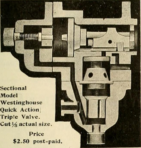
Image by Internet Archive Book Photos
Identifier: railwaylocomotiv18newy
Title: Railway and locomotive engineering : a practical journal of railway motive power and rolling stock
Year: 1901 (1900s)
Authors:
Subjects: Railroads Locomotives
Publisher: New York : A. Sinclair Co
Contributing Library: Carnegie Library of Pittsburgh
Digitizing Sponsor: Lyrasis Members and Sloan Foundation
View Book Web page: Book Viewer
About This Book: Catalog Entry
View All Pictures: All Pictures From Book
Click here to view book on the web to see this illustration in context in a browseable on the internet version of this book.
Text Appearing Ahead of Image:
Computer is in a neat folding, leather-cov-ered case. A single side provides formula and dircctionifor use. The other side has a graduated circleupon which turns a graduated card disc. Ctt.r b« Adjusted In a. Momentto Give Result With no Calculation THIS OFFICEPrice. .00 Eetch Model Locomotives and Castingfs Better than ever! Most current N. Y. Cen.Common. High Saddles —Bg Drivers—4 sizes Anything further nice. 4c. instamps for catalog. . S.P. O. Box 2«8. CAn Bl LL. Monllcello, N. Y October, 1905. RAILWAY AND LOCOMOTIVE ENGINEERING 481 AIR BRAKE MODELS For Self Instruction. WITH CHART. AIK CHAMBHKS CI)I.ORi:il.AI.I, Parts NIIMHKRKI). Improved Portable Boring, Milling andDrilling Machine. Tlic Espcii-Lucas Maclunc Business,of Philadelpliia, has just placed on themarket many improved portable ma- lls range of speeds ctnbraccs every re-(liiisite from the smallest drill to thelargest cutter. The materials are all ofthe extremely ideal, the spindle becoming ofhammered crucible steel 4 ins. in diam-
Text Appearing Right after Image:
SectlonalModel WestinghouseQuick ActionTriple Valve.Cut 14 actual size. Cost.50 post°paJcL Manufactured by W. VAN NAME 360 Evergreen Ave., BROOKLYN, N. Y. imEljmoN SWITCH &SIGNAL CO. Consulting and ManufacturingSignal Engineers Automatic Block Signals—Electricand Electro-Pneumatic Interlocking—Electric, Electro-Pneu-matic and Mechanical Electric Train Staff Apparatus General OFFICES AND Operates ATSWISSVALE, PA. DISTRICT OFFICES: New York: 143 Liberty StreetChlca]o: nitnadnock Block5t. Louis : Frisco Developing Patents. QEO. P. WHITTLESEY McQILL BUILOINQ WASMINQTON, D. C. Terms Affordable. Pamphlet Sent
Note About Pictures
Please note that these pictures are extracted from scanned web page photos that may have been digitally enhanced for readability – coloration and appearance of these illustrations may not perfectly resemble the original operate.
Engraving machine
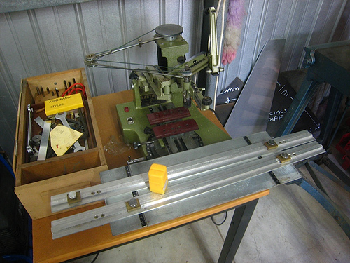
Image by brotherlywalks

China International Sheet Metal Market Expo? Important Subject – Cnc Machining Gear, Casting,
China International Sheet Metal Market Expo? Important theme
China International Sheetmetal Industry Exposition
2010 China (Shenzhen) International CNC machining equipment and casting, forging Exhibition and Conference
Date: May 2010 28 – 30 Venue: Shenzhen Convention & Exhibition Centre
Supervised by: Shenzhen Municipal People’s Government
Organizer: China International Sheet Metal Market Association, three Department of International Group Co., Ltd.
Sponsor: Third Meeting of Guangdong International Exhibition Co., Ltd.
Particular help: Shenzhen China Hi-Tech Exchange Center
Theme: green manufacturing and technological innovation
Market place trends
Along with CNC machining equipment manufacturing sector and the large demand for modern day manufacturing tactics in order to obtain the increasing demands of NC technologies, high speed, higher precision, high intelligence, higher automation is the future of CNC machining gear trends our national defense, aviation, space business development and energy business gear and other standard wants of large and powerful efficiency of numerical handle gear, excellent assistance, at present, CNC equipment, has turn into the national economy and national defense construction and improvement of main gear.
The metal casting business as the major method and indicates of processing, is a colossal critical industries, automotive, petrochemical, steel, electric power, shipbuilding, textiles, military, aviation, aerospace, equipment manufacturing and other pillar industries are primarily based, are an critical portion of the manufacturing sector. With the automobile, aircraft development and continuous improvement of environmental protection requirements, to the metal forming technology is also a greater demand. Product intensive production, development of personality, power requirements, environmental needs, will lead to metal forming business, a new round of technological innovation and transformation of casting the new technologies, new components, new gear, study, improvement, environmental protection kind casting of the original and auxiliary supplies is to market the value of holding this exhibition, one particular of the motives, settling in low energy consumption and raw material consumption, use of renewable components and power, to ensure the sustainable improvement of foundry sector to accomplish self-innovation, green, green casting is this exhibition and forums focused on the topic. Meanwhile, also the foundry industry’s future technologies and marketplace improvement.
Operate collectively to lead the market
Hold “2010 China (Shenzhen) International CNC machining gear and casting, forging Exhibition and Conference”, to meet the existence of China, especially southern China, held a enormous marketplace demand. For the fast increasing Chinese market, via our organized exhibitions, conferences and promotional activities for far more enterprises to produce valuable company possibilities in China, Guangdong province, organized the very first economic “FNCEF2010”, organizers hope that the enterprises in this In the course of the exhibition shows the most advanced CNC machining equipment and casting, forging and industrial chain products, in time for the domestic and international consumers the top of the world’s most cutting-edge technologies solutions and CNC machining gear for the nation and casting, forging and purchasing departments to provide top quality products and solutions and solutions the very same time promoting our CNC machining equipment and casting, forging and upgrading equipment as CNC machining and casting, forging specialist and technical fields the strongest, most close to the market leader in activities! Whether or not you are a company choice makers, technical choice makers, or technical specialists, development group, developers, general customers, “FNCEF2010” will bring you each outstanding knowledge and value.
Casting and CNC gear pros Promotion
Live show has set up higher-level personnel area, to attract a lot more expert talent casting and CNC technologies enterprises to participate in the field, the field of enterprises with more talent to our casting and CNC manufacturing sector with powerful technical talent help.
On the “2010 China International Sheet Metal Business Expo”
“FNCEF2010” is “2010 Sheet Fair,” one particular of the critical topics, “FNCEF2010” and “Sheet Metal Expo 2010” held in the exact same field, will show the resources to attain complementary mainly deals with the acquire of raw components — Bending Forming — welding (assembly) spray — — — service delivery, comprehensive show of sheet metal processing and industrial fields as properly as the whole approach chain exhibition, the region of the globe sheet metal business producers display new technology new gear enhance corporate image, sheet metal market requirements to recognize China, and to find Cooperation Partners, develop the market constructed a good platform for exchange and cooperation.
I am China Producers writer, reports some details about threaded pin , threaded aluminum rod.
Discover Far more China Sheet Metal Articles

Cool Machining Engineering pictures
A few good machining engineering images I discovered:
Image from page 340 of “Engineering and Contracting” (1909)
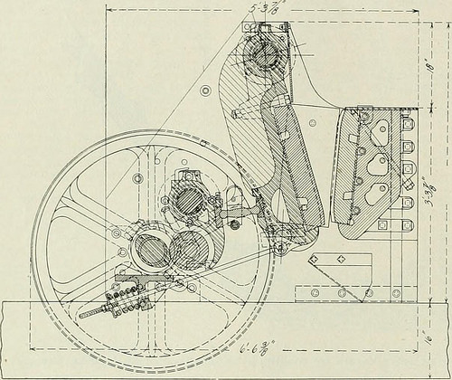
Image by Net Archive Book Pictures
Identifier: engineeringcontr33chicuoft
Title: Engineering and Contracting
Year: 1909 (1900s)
Authors:
Subjects:
Publisher: Chicago
Contributing Library: Gerstein – University of Toronto
Digitizing Sponsor: MSN
View Book Page: Book Viewer
About This Book: Catalog Entry
View All Pictures: All Images From Book
Click here to view book on the internet to see this illustration in context in a browseable on-line version of this book.
Text Appearing Just before Image:
er, Wyo. T. E. Calvert,Chicago, 111., is chief engineer. 200 ENGINEERING-CONTRACTING Vol. XXXIII. No. q. A New Jaw Crusher Made Particu-larly for Contractors Use. .A. crusher for contractors use has to ful-fill distinct specifications than are intendedfor general quarry use. A contractorscrusher should be of large output, remarkablylight in weight, convenient to deal with and aboveall really durable. Certain focus hasbeen paid to these qualities in designing thecrusher illustrated in the accompanying cut.A notable function of this machine is its prac- Approach of Generating a Steam Shovel Cutof Two Lifts in 1 Lift. BY H. MORTON STEPHENS.* During September, 1909. the E. Purcell Con-struction Co., secured from the Winston-Salem South Bound Ry. Co., a contract forthe building of part of tJie above railroad,embracing sections 22 to 30 inclusive. Section22 is positioned in the town of Lexington, N. C,on the Southern Ry. The balance of the workruns south by way of a rolling country, and with
Text Appearing Soon after Image:
A New Jaw Crusher for Contractors. tically all-steel construction. The major frameor side plates are of rolled steel plates. Thelarge casting that forms the front of themachine, which part is termed the stationaryjaw, is of grey iron. The moving or swingingjaw is a steel casting. The tumbler or largelever casting is also of steel. The fly wheelsand pedestals are of grey iron. The maincam shaft and the anti-friction roller are steelforgings. The anti-friction roller revolvesin boxes produced of unique bronze material. Allshafts from which castings are suspended areof steel. The cheek plates are of unique har-dened steel, although the toggle seats are alsomade of unique steel. This steel construction makes the machineof tremendous strength in comparison withits size. The feeding mouth is reduce, in fact,than in other crushers of equal size. Thismeans that a huge saving is effected in deliv-ering stone into the crusher. The crusherwill turn out from 150 to 200 tons of crushedmaterial per day
Note About Photos
Please note that these photos are extracted from scanned page images that may have been digitally enhanced for readability – coloration and appearance of these illustrations may possibly not completely resemble the original work.
Image from web page 490 of “Railway and locomotive engineering : a sensible journal of railway motive power and rolling stock” (1901)
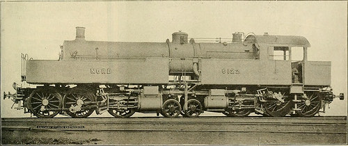
Image by World wide web Archive Book Images
Identifier: railwaylocomotiv19newy
Title: Railway and locomotive engineering : a practical journal of railway motive energy and rolling stock
Year: 1901 (1900s)
Authors:
Subjects: Railroads Locomotives
Publisher: New York : A. Sinclair Co
Contributing Library: Carnegie Library of Pittsburgh
Digitizing Sponsor: Lyrasis Members and Sloan Foundation
View Book Web page: Book Viewer
About This Book: Catalog Entry
View All Pictures: All Photos From Book
Click here to view book on-line to see this illustration in context in a browseable on the internet version of this book.
Text Appearing Ahead of Image:
ops, as a result loses a gooddeal of its mobility. The two motortrucks o.f our locomotive are truebogies, totally free to assume all|)ositions on the track. Its boiler rests1111 a frame produced of a beamiif which tlie ends are enlarged Exhibits, Traveling EngineersConvention. American Locomotive Equipment Co.,Chicago, showed a chart of test of thehollow arch compared with the solidarch and no arch. S. F. Bowser & Co., Inc., Fort Wayne,Ind., distributed circulars showingBowser oil storage method as utilised at lo-comotive stations. Century Preserver Co. distributed,by way of their sales agent, W. A. Ahrens,Chicago, some literature concerningtheir black metal preserver for coveringIhe exposed surfaces of metal. The Chicago Pneumatic Tool Com-pany have just issued their new Com-pressor catalogue consisting of 118p?ges, printed in two colors. Severalnew sorts and sizes of Compressors areshown in this catalogue including theirItw Hamilton Corliss Machines. Thoseinterested will obtain copy upon re-
Text Appearing Soon after Image:
TANK ENGINE FOR THE CHEMIN DE FER DU NORD, FRANCE. ins. The diameter of the boiler is 51ins. There are 130 tubes every about 15ft. 7 ins. long and there is a total heat-ing surface of tubes and fire box of2,361 sq. ft. The pressure carried is228 lbs. to the square inch. Steam fromthe boiler goes to the cylinders andthrough them to the smoke box throughthe steam pipe which runs from thedome down to a swivel joint placed overthe kingpin of the truck with its axisin line with the kingpin. From the highpressure cylinders it goes to the lowpressure cylinders via a length offlexible pipe. The exhaust is led to thesmoke box by way of one more swivel jointin the center of the truck carrying thelow pressure cylinder. An arrangementis created whereby both the high and thelow stress cylinders may be suppliedwith high pressure steam when neces-sary, in starting or on grades. In thiscase the engine operates as a basic and offered with signifies for at-taching the elastic springs. Thisarrangement, com
Note About Pictures
Please note that these photos are extracted from scanned web page images that may have been digitally enhanced for readability – coloration and appearance of these illustrations may not perfectly resemble the original operate.
Royal Engineers total construction of Afghan Nearby Police station in Helmand capital
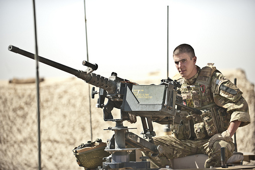
Image by DVIDSHUB
Highlander Mark Mackenzie, 4th Battalion, The Highlanders, Royal Regiment of Scotland, and a native of Stoneaway, Scotland, completes a final check of a .50-caliber mounted machine gun ahead of delivering security for 59 Commando Squadron, Royal Engineers, as they travel to construct an Afghan Neighborhood Police station in Lashkar Gah District, Helmand province, July 24. The Engineers constructed the station for the Afghan Nearby Police, a local safety force produced up of hand-picked people from the neighborhood.
Regional Command Southwest
Photo by Petty Officer 2nd Class Jonathan Chandler
Date Taken:07.24.2011
Place:HELMAND PROVINCE, AF
Connected Pictures: dvidshub.net/r/khgcep

GB 8624-1997 normal fireproof components – refractory – Precision Fasteners – CNC Machining Parts
GB 8624-1997 requirements for fire prevention materials
Common variety Normal Name (English) Normal No. Standard Issued Release Date Common
Date Standards Common text Foreword This standard is GB8624-88 revision. Non-equivalent in technical content material, utilizing the German standard
DIN4102-81 Component. The revision, compared with the GB8624-88, the addition of A-level composite (sandwich) supplies, and according to my
Nation-particular circumstances, an enhance of the certain uses of flooring, curtains and curtain variety textiles, wire and cable casing
Class plastic supplies and pipe insulation foam employed specified. If the specific use of supplies as
Wall or ceiling supplies used, nevertheless should be Chapter 4 of the normal provisions of Chapter 5 of the inspection and grading.
This standard from the efficient date of the original GB8624-88 shall be invalid. The People’s Republic of China Ministry of Public Security
This normal is raised. This common by the National Fire Protection Standardization Technology Committee Sub-Committee under the jurisdiction of the seventh.
The standard Ministry of Public Safety of Sichuan Fire Research Institute is accountable for drafting.
Main drafters of this normal: Qian Jianmin, Ma Xianglin, Lu National Development.
The normal initial released in February 1988.
The People’s Republic of China national standard
GB 8624-1997 Classification flammability of creating supplies
Instead of GB 8624-88 Classification on burning behaviour for developing supplies
1 Subject Matter and Scope This normal specifies the combustion properties of materials evaluation and classification standards.
This common applies to all kinds of industrial and civil engineering structures used in a assortment of decorative materials and gear
Repair components. two Normative references Following requirements contain provisions which, by means of reference in this regular, constitute the standard provisions. The normal
Time of publication, the editions indicated had been valid. All requirements are topic to revision, the parties need to discover the normal so that
With the possibility of the most recent version of the following criteria.
GB/T2406-93 Test technique for flammability of plastic oxygen index
GB/T2408-80 Test approach for flammability of plastic the level of combustion
GB/T4609-84 Test technique for flammability of plastic vertical burning
GB/T5454-85 burning properties of textile fabrics Determination of oxygen index
GB/T5455-85 Determination of vertical flame retardant textile fabrics technique
GB/T5464-85 not flammable building materials test methods
GB/T8332-87 foam combustion behavior of horizontal combustion
GB/T8333-87 challenging foam combustion vertical burning test strategies
GB/T8625-88 flammability for building materials test approach
GB/T8626-88 materials flammability test strategies
GB/T8627-88 combustion or decomposition of materials test methods for smoke density
GB/T8629-88 test used in the family textile washing and drying procedures
GB/T11785-89 paving Crucial Radiant Flux from a radiant heat source technique
GB/T14402-93 Test technique of heat burning constructing supplies
GB/T14403-93 combustion heat test techniques for constructing materials
three level of flammability of constructing components and name
Level of flammability of constructing components and names in Table 1.
Table 1 Combustion level and name
-Level name A noncombustible components B1 flame retardant supplies B2 combustible materials B3 flammable supplies Bureau of Technical Supervision 1997-04-04 1997-10-01 authorized the implementation of
GB 8624-1997 4 non-combustible type material (A Grade)
four.1 A homogeneous material level
By GB/T5464 test, the fuel properties to be accomplished:
A) the furnace typical temperature rise of not much more than 50
B) the sample continued to burn an average of no a lot more than 20s
C) The typical mass loss rate of the sample does not exceed 50%.
four.2 A class of composite (Sandwich) materials
Meet the following requirements of the material, its combustion properties as A-level.
A) by GB/T8625 testing, every single specimen, the average remaining length of 35cm (including any of the specimens
The remaining length of> 20cm), and the average gas temperature of every single test peak 125 , the sample on the back with out any fuel
Burning phenomenon B) by GB/T8627 test, the smoke density rating (SDR) 15
C) by GB/T14402 and GB/T14403 test, its thermal worth four.2MJ/kg, and specimen
The e-commerce business in China provides quality items such as Precision Fasteners , CNC Machining Components, and much more. For much more , please check out machining components Manufacturer these days!

Cool Machining Engineering images
Some cool machining engineering pictures:
Machine
Image by MattyGregs
scary

Image by John Christian Fjellestad
Skull fabric
Image by Cross-stitch ninja
Crappy, crappy mobile telephone pic, but I am so excited about this! It was the very first time we had been permitted to use the huge knitting machines at school!
We did everything, from designing the pattern to setting the machine. This is what I’ve been waiting for given that I decided to start off studying again.

Cool Machining Engineering images
Some cool machining engineering pictures:
Image from web page 485 of “American engineer and railroad journal” (1893)
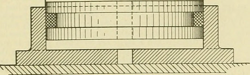
Image by World wide web Archive Book Photos
Identifier: americanengineer68newy
Title: American engineer and railroad journal
Year: 1893 (1890s)
Authors:
Subjects: Railroad engineering Engineering Railroads Railroad cars
Publisher: New York : M.N. Forney
Contributing Library: Carnegie Library of Pittsburgh
Digitizing Sponsor: Lyrasis Members and Sloan Foundation
View Book Web page: Book Viewer
About This Book: Catalog Entry
View All Photos: All Pictures From Book
Click right here to view book on-line to see this illustration in context in a browseable on the internet version of this book.
Text Appearing Before Image:
qually satisfactory. The tiny enginedrives drills and valve-facing tools straight by implies of theStow flexible shaft. The identical practise also prevails here, ason the other road, in the building of pistons. A hollowpislon with rings sprung in is employed, but the rings are muchnarrower than on the New York, Lake Erie & Western. Mr.Foster makes use of a ring only | in. wide, and finds them perfectlysatisfactory. There is a strategy of holding the split rings out 496 THE AMERICAN ENGINEER [November, 1894. right here, nonetheless, that—to us at least—is novel. It is well knownthat if a ring is turned to a bigger diameter than that of thecylinder in which it is to run, when it is sprung in it will beout of round. To obviate this difficulty and, at the same time,hold an outward pressure on the ring, it is turned to match thecylinder. Yet another and slightly heavier ring is turned to adiameter a trifle bigger than the inside of the outer ring, andthe outer ring slipped more than it. Then, wheu they are both com-
Text Appearing Soon after Image:
BALANCED VALVE, FALL BROOK COAL CO. pressed and place in thecylinder, the outer ring is round, whilethe inner keeps it nicely out against the walls. The vehicle shops adjoin the machine shop, and are fitted withthe usual complement of woodworking tools. The floor roomconsists of three tracks, each capable of holding 5 automobiles. AllCars coming in for rebuilding and all new rolling stock areequipped with the Gould coupler and the Westinghouse airbrake. The nicknames bestowed up-on a variety of varieties of locomotivesby the men constructing or runningthem have come to have a trulytechnical significance but it is sel-dom that a nickname is acceptedby the motive energy departmentwith the gravity of a name appliedto one particular of the locomotives on thisroad. All the engines have namesas nicely as numbers, although theformer are a mere ornament andnot used in reports or orders. Acertain locomotive had the misfor-tune to jump from a high trestle atIthaca, and was forthwith dubbedthe Sam Patrh by the males. Re-pairs naturally
Note About Pictures
Please note that these pictures are extracted from scanned page images that might have been digitally enhanced for readability – coloration and appearance of these illustrations may possibly not completely resemble the original work.
Image from page 423 of “Manual for railroad engineers and engineering students : containing the guidelines and tables necessary for the location, building, and equipment of railroads as constructed in the United States” (1883)
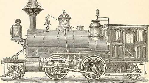
Image by Web Archive Book Pictures
Identifier: manualforrailroa00vose
Title: Manual for railroad engineers and engineering students : containing the rules and tables needed for the place, building, and equipment of railroads as constructed in the United States
Year: 1883 (1880s)
Authors: Vose, George L. (George Leonard), 1831-1910
Subjects: Railroad engineering
Publisher: Boston : Lee and Shepard
Contributing Library: Northeastern University, Snell Library
Digitizing Sponsor: Northeastern University, Snell Library
View Book Page: Book Viewer
About This Book: Catalog Entry
View All Images: All Pictures From Book
Click right here to view book on-line to see this illustration in context in a browseable on-line version of this book.
Text Appearing Before Image:
Fig- 157- Fig. 157 and the addition of a related truck behind gives thetank engine, made by Mr. Hudson, of the Rogers Locomotive 398 MANUAL FOR RAILROAD ENGINEERS. Functions, shown in Fig. 158, a most excellent machine for switching,construction, branch, and even light passenger service.*
Text Appearing Soon after Image:
Fig. 158. Iig- 1S9 shows a six-wheeled tank engine, which, upon a toler-ably straight track, is a quite effective machine, but upon sharp
Note About Images
Please note that these images are extracted from scanned web page photos that may possibly have been digitally enhanced for readability – coloration and look of these illustrations may not completely resemble the original work.

Good Machining Engineering images
A couple of nice machining engineering images I identified:
US Navy Cryptanalytic Bombe
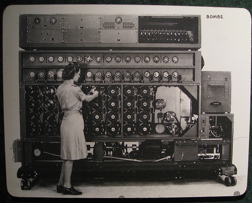
Image by brewbooks
A US Navy WAVE sets the Bombe rotors prior to a run
The US NAvy cryptanalytic Bombes had only one particular purpose: Decide the rotor settings utilized on the German cipher machine ENIGMA. Initially created by Joseph Desch with the National Cash Register Firm in Dayton, Ohio, the Bombes worked mainly against the German Navy’s four-rotor ENIGMAs. Without the correct rotor settings, the messages were practically unbreakable. The Bombes took only twenty minutes to complete a run, testing the 456,976 feasible rotor settings with a single wheel order. Various Bombes attempted various wheel orders, and a single of them would have the final appropriate settings. When the a variety of U-boat settings have been identified, the Bombe could be switched over to operate on German Army and Air Force 3-rotor messages.
Supply: National Cryptologic Museum
Comment on the above
The 4 rotor program had 26^4 or 456,976 settings whilst the theree rotor technique had 26^three or 17,756 settings. It appears like the dilemma scale in a linear way as it took 50 seconds to verify 17,756 setting (~350 per second) whilst the 4 rotor resolution in 20 minutes is ~ 380 settings per second.
I also think the designer Joseph Desch sounds like a remarkable engineer that I never ever heard of just before.
Bombe on Wikipedia
As soon as the British had offered the Americans the information about the bombe and its use, the US had the National Cash Register Company manufacture a great several extra bombes, which the US then utilised to help in the code-breaking. These ran significantly quicker than the British version, so quick that as opposed to the British model, which would freeze quickly (and ring a bell) when a attainable answer was detected, the NCR model, upon detecting a feasible remedy, had to "remember" that setting and then reverse its rotors to back up to it (meanwhile the bell rang).
Source of following material : National Cryptologic Museum
Diagonal Board is the heart of the Bombe unit. Electrically, it has 26 rows and 26 columns of points, each with a diagonal wire connection. These wires connect every single letter in a column with the exact same position in each and every row. A letter cannot plug into itself these are recognized as "self-steckers." The resulting pattern is a series of diagonal lines. The purpose of the diagonal board is to eliminate the complications brought on by the Enigma’s plugboard. Provided particular rotor settings, only specific plugboard settings can result in the proper encrypted letter. The diagonal board disproved hundreds of rotor settings, permitting for only a handful of possibly right settings to outcome in a "strike".
Amplifier Chassis had two purposes, very first to detect a hit and second to decide if it was useful. It supplied the tie-in from the diagonal board, the locator, and the printer circuits.
Thyratron Chassis was the machine’s memory. Considering that the wheels spun at such a high speed, they could not instantly quit rotating when a correct hit was detected. The Thyratron remembered exactly where the appropriate hit was located and indicated when the Bombe has rewound to that position. It also told the machine when it had completed a run and gave the final stop signal.
Switch Banks tell the Bombe what plain to cipher letters to search for. Utilizing menus sent to the Bombe deck by cryptanalysts, WAVES set each dial making use of unique wrenches. 00 equates to the letter A and 25 to the letter Z. The dials work together in groups of two. 1 dial is set to the plain test letter and the other to its corresponding cipher letter as determined by cryptanalysts. There are sixteen sets of switch banks, however, only fourteen had been required to comprehensive a run. As the machine worked through the rotor settings, a correct hit was possible if the electrical path in all fourteen switch banks corresponded to every of their assigned plaintext/cipher combinations.
Wheel Banks represent the 4 rotors used on the German U-boat Enigma. Every column interconnects the 4 rotors, or commutators, in that column. The leading commutator represented the fourth, or slowest, rotor on the Enigma, although the bottom wheel represented the rightmost, or fastest, rotor. The WAVES set the rotors according to the menu developed by the cryptanalysts. The 1st have been set to 00, and each set soon after that corresponded to the plain/cipher hyperlink with the crib (the assumed plain test corresponding to the cipher text.) Normally this meant that each wheel bank stepped up one spot from the 1 on its left. When the machine ran, each bottom rotor stepped forward, and the machine electrically checked to see if the assigned situations had been met. If not, as was generally the case, every bottom wheels moved 1 a lot more place forward. Nonetheless, the bottom commutator moved at 850 rpm, so it only took twenty minutes to full a run of all 456,976 positions.
Printer automatically printed the details of a attainable hit. When the Bombe determined that all the possible conditions had been met. it printed wheel order, rotor settings and plugboard connections.
Motor Manage Chassis controlled both forward and reverse motors. The Bombe was an electromechanical machine and needed a number of gauges for monitoring. It also necessary a Braking Assembly to slow the forward motion when a hit was detected and to bring the machine to a complete quit when a run was completed.
i09_0214 129
Engraving machine
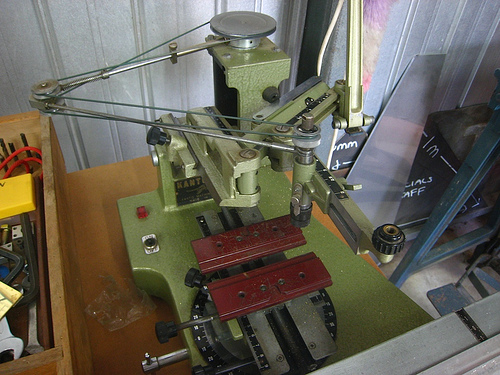
Image by brotherlywalks

Most recent Machining Engineering News
Concrete eating monster

Image by John Christian Fjellestad
Latest Machining Engineering News
Concentric Cogs

Image by Jamie Dobson Photography
An exhibit at Bradford’s Industrial Museum
Prototype with Overmolding, Liquid Silicone Rubber, and Multi-Axis Machining
Engineers often locate themselves in a rush to get a prototype of their part. They can find a local 3D print service, hope a machine shop will fit their single part onto a CNC machine, or hunt down a custom mold shop. Alternatively, they can upload their …
Read far more on ENGINEERING.com
3D Printing, CNC Machining or Molding: What's Greatest for Your Prototype?
As a reference, Holtz presented the following rule of thumb: “3D printing is generally a price-effective selection for up to about 50 components and CNC machining is economical for up to about 200, but our common single-cavity molds can normally generate up to …
Read a lot more on ENGINEERING.com