Nice Higher Precision Engineering images

Nice Higher Precision Engineering images

Check out these higher precision engineering photos:

AF Memorial_Light the Night
high precision engineering
Image by catface3
Air Force Memorial, Washington, DC, on a hill overlooking the Pentagon. Subsequent to Arlington National Cemetery and to Ft Myer, Virginia, exactly where the Wright brothers 1st demonstrated their Flyer for the Army.

en.wikipedia.org/wiki/United_States_Air_Force_Memorial

&quotThe Memorial itself is 270 feet (82 m) higher and appears to be soaring its array of stainless steel arcs against the sky evokes the image of &quotcontrails of the Air Force Thunderbirds as they peel back in a precision ‘bomb burst’ maneuver.&quot Only three of the 4 contrails are depicted, as the absent fourth evokes the missing man formation traditionally utilised at Air Force funeral fly-overs.&quot
&quotThe spire structure consists of stainless steel plates with high-strength concrete filling the lower 2/3rds of every single spire. The upper third is hollow stainless steel.[six] At the transition amongst concrete and hollow steel portions, dampers are offered to dissipate wind sway power and eradicate the threat of aerodynamic instability. Every single damper consists of a lead ball weighing about a ton each and every, allowed to roll inside a steel box. The structural design of the memorial was completed by engineering.&quot

Aluminum Higher Stress Die Casting

Aluminum Higher Stress Die Casting

Aluminum is a really critical metal in manufacturing, and this is simply because of its versatile properties and the different applications of each the processed metal and its alloys in distinct industries.

High stress die casting enables the quickest route from molten metal to the completed element. This is achieved by injecting molten metal into a hardened tool steel mould, and enabling it to cool and solidify beneath pressure prior to it is removed. This procedure gives a precise, fast cost successful approach of production for aluminum or zinc die castings, which meets the demands and needs of hi-tech industries exactly where the appearance of the solution and the the dimensional tolerances are essential and volumes are not usually big.

Aluminum is employed in the process of aluminum high pressure die casting, and is a metal that has a lot of positive aspects which is excellent for use in the casting of metal alloys. One particular of the many causes that aluminum is is used in the die casting process is the properties of the metal itself. Aluminum has a quantity of characteristic attributes which are perfect for this method. Aluminum is really light in weight and and highly ductile and can effortlessly be beaten into different shapes and sizes depending on the requirements and specifications. It is also really malleable and has quite very good dimensional stability permitting it to attain complicated shapes and thin walled elements. Aluminum is dust and corrosion resistant and has excellent electronic properties and exceptional thermal characteristics, and because it is a great conductor of heat it is capable to retain the heat and and take good shape in the cast.

Stress die casting is a competitive casting method when elements are necessary in higher volumes, or when tighter tolerances and greater high quality surface finishes are needed that can be accomplished by gravity die casting. Also the need to have for machining is very low due to the close casting tolerances. Heat therapy of pressure die casting is not possible, but due to the high price of solidification the mechanical properties are very good, even so the tooling costs are considerably greater than they are for gravity die casting.

Ther are several various die casting alloys and these contain: aluminum, zinc, lead, copper, magnesium and tin. Two dies are used for casting the cover dies half and the ejector dies half, and where they meet is known as the ‘parting line’. The dies are created to allow the completed casting to slide off the cover half of the die and remain in the ejector half as the dies are opened.

Other die elements consist of slides and cores. The cores are elements that typically produce openings or holes, but they can be employed to generate other specifics as properly. There are 3 types of cores, loose, movable and fixed. Loose cores are employed to generate intricate details and are inserted into the die by hand. Fixed cores are oriented parallel to the pull path of the dies, and are permanently attached to the die. Movable cores are oriented in any other way than parallel to the pull path. They are removed from the die cavity right after the shot solidifies.

Anthony Pateman from RD Castings Ltd writes about Die Casting. For far more details about Die Casting visit www.rdcastings.co.uk

Zinc Higher Pressure Die Casting

Zinc Higher Pressure Die Casting

The process of higher stress zinc die casting can be divided into two approaches. Cold chamber die casting and hot chamber die casting, and the major difference amongst them is the distinct variety of machines that are employed. Normally, hot chamber machines are a lot more suitable for small and light zinc items, although cold chamber die casting machines are generally utilised to manufacture massive heavy die casting products.

The hot chamber die casting method has been around a bit longer than the cold chamber die casting process, and it is best for the casting of copper, lead and zinc alloys. The hot chamber sort of machine is more suitable for for casting small size die items, and quite generally the hot chamber method will have a much more quickly speed than the cold chamber process. The hot chamber method is not truly appropriate for massive and heavy die cast merchandise.

For the duration of the hot chamber die casting procedure, the molten alloy is pressed into the die cavity, right after the cavity has been filled the surplus molten alloy flows back to the furnace along with stress release. With a little size die cast product, a hydraulic shot cylinder is applied which will finish the injection at once.

Right after the injection of molten alloy, the alloy filling the cavity cools with the application of a water cooling method, and the surplus alloy flows back to the furnace. Hot chamber die cast parts typically have a significantly smaller sprue, and quicker casting speeds than the cold chamber die casting approach. This sort of die casting method is best for lead, copper and zinc alloys. For the production of zinc and zinc alloy castings the dies are usually manufactured from unalloyed steel, and for aluminium, copper, magnesium and the alloys of these metals, the dies are usually produced from hot work tool steel since of its higher durability.

A total cycle of the process will perform as therefore: the die is closed and molten metal is forced into it, the cores are withdrawn, the die is opened, the casting is ejected and if needed any shearing off the sprue and deburring the casting, then the die is cleaned. The number of cycles per hour that can be accomplished depends on a quantity of distinct factors: casting metal utilized and size and shape of the casting.

With zinc alloys it is possible in a provided period of time to create numerous a lot more castings per hour than it is to make castings which are created from brass. Zinc pressure die casting tends to make achievable the economical production of detailed castings at a really fast price. The castings can comprise of particulars such as holes, recesses and so on, and are characterized by good surface finish, higher dimensional accuracy and the economy of the metal. There are completely automated machines which can turn out thousands of little zinc alloy castings per hour. The machines could be pneumatically operated or the pressure may be created by the action of a ram.

Anthony Pateman from RD Castings Ltd writes about Zinc HPD Die Casting. For far more information about Zinc HPD Die Casting visit www.rdcastings.co.uk

Uncover More Die Casting China Articles

Cool Higher Precision Engineering images

Cool Higher Precision Engineering images

Check out these high precision engineering pictures:

Steven F. Udvar-Hazy Center: South hangar panorama, such as Vought OS2U-three Kingfisher seaplane, B-29 Enola Gay
high precision engineering
Image by Chris Devers
Quoting Smithsonian National Air and Space Museum | Vought OS2U-3 Kingfisher:

The Kingfisher was the U.S. Navy’s primary ship-based, scout and observation aircraft throughout Globe War II. Revolutionary spot welding strategies gave it a smooth, non-buckling fuselage structure. Deflector plate flaps that hung from the wing’s trailing edge and spoiler-augmented ailerons functioned like further flaps to allow slower landing speeds. Most OS2Us operated in the Pacific, exactly where they rescued numerous downed airmen, including World War I ace Eddie Rickenbacker and the crew of his B-17 Flying Fortress.

In March 1942, this airplane was assigned to the battleship USS Indiana. It later underwent a six-month overhaul in California, returned to Pearl Harbor, and rejoined the Indiana in March 1944. Lt. j.g. Rollin M. Batten Jr. was awarded the Navy Cross for generating a daring rescue in this airplane beneath heavy enemy fire on July four, 1944.

Transferred from the United States Navy.

Manufacturer:
Vought-Sikorsky Aircraft Division

Date:
1937

Nation of Origin:
United States of America

Dimensions:
Overall: 15ft 1 1/8in. x 33ft 9 1/2in., 4122.6lb., 36ft 1 1/16in. (460 x 1030cm, 1870kg, 1100cm)

Supplies:
Wings covered with fabric aft of the major spar

Physical Description:
Two-seat monoplane, deflector plate flaps hung from the trailing edge of the wing, ailerons drooped at low airspeeds to function like further flaps, spoilers.

• • • • •

Quoting Smithsonian National Air and Space Museum | Boeing B-29 Superfortress &quotEnola Gay&quot:

Boeing’s B-29 Superfortress was the most sophisticated propeller-driven bomber of Globe War II and the very first bomber to house its crew in pressurized compartments. Although created to fight in the European theater, the B-29 located its niche on the other side of the globe. In the Pacific, B-29s delivered a assortment of aerial weapons: conventional bombs, incendiary bombs, mines, and two nuclear weapons.

On August 6, 1945, this Martin-constructed B-29-45-MO dropped the first atomic weapon utilised in combat on Hiroshima, Japan. Three days later, Bockscar (on display at the U.S. Air Force Museum close to Dayton, Ohio) dropped a second atomic bomb on Nagasaki, Japan. Enola Gay flew as the advance climate reconnaissance aircraft that day. A third B-29, The Fantastic Artiste, flew as an observation aircraft on each missions.

Transferred from the United States Air Force.

Manufacturer:
Boeing Aircraft Co.
Martin Co., Omaha, Nebr.

Date:
1945

Nation of Origin:
United States of America

Dimensions:
All round: 900 x 3020cm, 32580kg, 4300cm (29ft six five/16in. x 99ft 1in., 71825.9lb., 141ft 15/16in.)

Supplies:
Polished overall aluminum finish

Physical Description:
Four-engine heavy bomber with semi-monoqoque fuselage and higher-aspect ratio wings. Polished aluminum finish all round, normal late-World War II Army Air Forces insignia on wings and aft fuselage and serial quantity on vertical fin 509th Composite Group markings painted in black &quotEnola Gay&quot in black, block letters on reduced left nose.

Nice Higher Precision Engineering photographs

Nice Higher Precision Engineering photographs

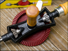
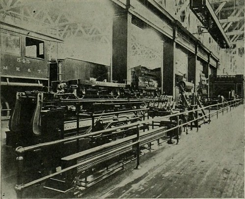
A handful of nice high precision engineering photos I identified:

Image from page 240 of “The Bell System technical journal” (1922)
high precision engineering
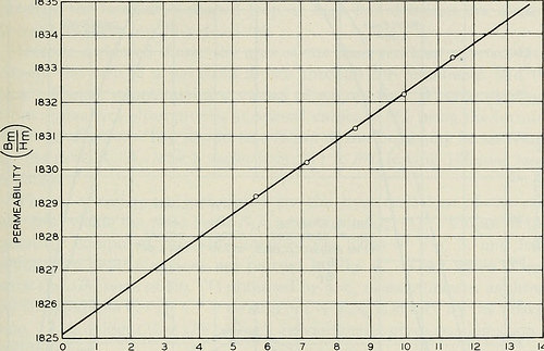
Image by Net Archive Book Photos
Identifier: bellsystemtechni16amerrich
Title: The Bell Program technical journal
Year: 1922 (1920s)
Authors: American Telephone and Telegraph Company
Subjects: Telecommunication Electric engineering Communication Electronics Science Technologies
Publisher: [Quick Hills, N.J., and so on., American Phone and Telegraph Co.]
Contributing Library: Prelinger Library
Digitizing Sponsor: World wide web Archive

View Book Web page: Book Viewer
About This Book: Catalog Entry
View All Images: All Pictures From Book

Click here to view book on the web to see this illustration in context in a browseable online version of this book.

Text Appearing Just before Image:
an addi-tional 60-turn winding was used for checking the measurements in thelow-frequency variety. In either case the inductance was low enoughto depress any effect of distributed capacitance far below the precisionof the measurements. Measurements have been produced on a ten-ohm equal ratio arm inductance MAGNETIC LOSSES AT LOW FLUX DENSITIES 217 comparison bridge,^ and were verified at low frequencies employing a 1-ohmratio arm bridge. Calibration of the bridge and common coils wasefifected by creating measurements over the whole frequency range on acalibrated higher good quality air core coil substituted for the test coil. Themaximum correction essential on this account was about .1per cent of the resistance due to the magnetic core. The supply of alternating present was an oscillator-amplifier supply-ing approximately .four watt undistorted energy, calibrated for thesemeasurements against the Laboratories standard frequency. Thecurrent was adjusted by the insertion of resistance in series with the

Text Appearing Following Image:
5 6 7 eight 9 H IN OERSTEADS X ten^ Fig. 2—Core permeability as measured by the ballistic galvanometer. main of the bridge input transformer, and was measured by meansof a thermocouple amongst the transformer secondary and the bridge.The bridge unbalance was amplified by signifies of an impedancecoupled amplifier for the 10-ohm bridge, and by indicates of a resistancecoupled amplifier for the 1-ohm bridge. The amplified unbalance wasobserved by means of head phones at frequencies above 200 cycles, andby means of a vibration galvanometer at lower frequencies. The d.-c.balance required bridge current of about 3 m.a. in the test coil winding,and had the identical precision as the a.-c. balance, viz., db .0002 ohm.The inductance readings had been corrected for the air space within thewinding, and had a relative accuracy of about .03 per cent, and anabsolute accuracy of around .1 per cent. 218 BELL Method TECHNICAL JOURNAL D.-C. Final results The permeability n = BmjHm of the specimen is shown as a enjoyable

Note About Images
Please note that these images are extracted from scanned web page photos that might have been digitally enhanced for readability – coloration and appearance of these illustrations may possibly not perfectly resemble the original operate.

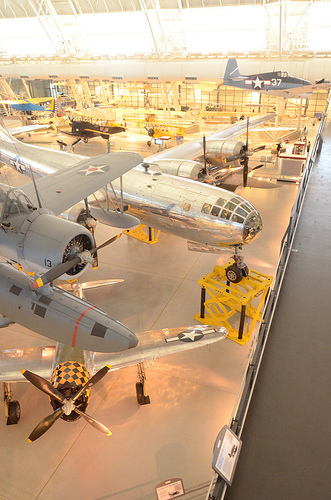
Boeing B-17 – Duxford Airshow Oct 2010
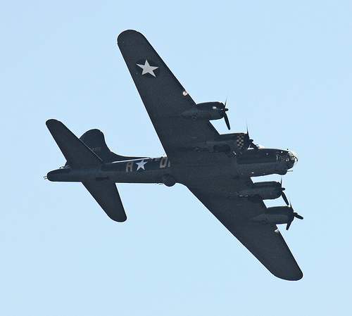
high precision engineering
Image by Feggy Art
Boeing B-17 at Duxford Airshow October 2010.

The Boeing B-17 Flying Fortress was a four-engine heavy bomber aircraft developed in the 1930s for the United States Army Air Corps (USAAC). Competing against Douglas and Martin for a contract to develop 200 bombers, the Boeing entry outperformed each competitors and a lot more than met the Air Corps’ expectations. Though Boeing lost the contract because the prototype crashed, the Air Corps was so impressed with Boeing’s style that they ordered 13 much more B-17s for additional evaluation. From its introduction in 1938, the B-17 Flying Fortress evolved through numerous style advances.

The B-17 was primarily employed by the United States Army Air Forces (USAAF) in the daylight precision strategic bombing campaign of Planet War II against German industrial and military targets. The United States Eighth Air Force primarily based at Thorpe Abbotts airfield in England and the Fifteenth Air Force primarily based in Italy complemented the RAF Bomber Command’s evening time area bombing in Operation Pointblank to assist safe air superiority more than the cities, factories and battlefields of Western Europe in preparation for Operation Overlord. The B-17 also participated to a lesser extent in the War in the Pacific exactly where it carried out raids against Japanese shipping and airfields.

From its pre-war inception, the USAAC (later USAAF) touted the aircraft as a strategic weapon it was a potent, high-flying, extended-variety bomber that was capable to defend itself, and to return house despite comprehensive battle harm. It rapidly took on mythic proportions, and widely circulated stories and photographs of B-17s surviving battle damage increased its iconic status. With a service ceiling higher than any of its Allied contemporaries, the B-17 established itself as an effective weapons system, dropping more bombs than any other U.S. aircraft in Planet War II. Of the 1.5 million metric tons of bombs dropped on Germany by U.S. aircraft, 640,000 tons had been dropped from B-17s.

Common characteristics

•Crew: 10: Pilot, co-pilot, navigator, bombardier/nose gunner, flight engineer-best turret gunner, radio operator, waist gunners (2), ball turret gunner, tail gunner
•Length: 74 ft four in (22.66 m)
•Wingspan: 103 ft 9 in (31.62 m)
•Height: 19 ft 1 in (5.82 m)
•Wing area: 1,420 sq ft (131.92 m2)
•Airfoil: NACA 0018 / NACA 0010
•Aspect ratio: 7.57
•Empty weight: 36,135 lb (16,391 kg)
•Loaded weight: 54,000 lb (24,500 kg)
•Max takeoff weight: 65,500 lb (29,700 kg)
•Powerplant: 4× Wright R-1820-97 Cyclone turbo supercharged radial engines, 1,200 hp (895 kW) each and every

Overall performance

•Maximum speed: 287 mph (249 kn, 462 km/h)
•Cruise speed: 182 mph (158 kn, 293 km/h)
•Range: 2,000 mi (1,738 nmi, 3,219 km) with two,700 kg (six,000 lb) bombload
•Service ceiling: 35,600 ft (ten,850 m)
•Rate of climb: 900 ft/min (four.six m/s)
•Wing loading: 38. lb/sq ft (185.7 kg/m2)
•Power/mass: .089 hp/lb (150 W/kg)

Armament

•Guns: 13 × .50 in (12.7 mm) M2 Browning machine guns in 4 turrets in dorsal, ventral, nose and tail, 2 in waist positions, two beside cockpit and 1 in the reduce dorsal position
•Bombs:
•Short range missions (&lt400 mi): 8,000 lb (three,600 kg)
•Long variety missions (≈800 mi): four,500 lb (two,000 kg)
•Overload: 17,600 lb (7,800 kg)

Text and specifications based on Wikipedia write-up below the Inventive Commons License for non-profit use.

This is the Boeing B17G-105-VE Flying Fortress 124485 G-BEDF (Memphis Belle)

Most current Higher Precision Engineering News

New Drone Stays by Your Side Using Sensible Watch Technologies
XWatch provides two approaches to command the drone to follow you. The 1st is a high-precision stress sensor that enables the user to command the aircraft to follow them by tapping when on the screen. The second selection is to verbally tell XEagle to follow you.
Read more on ENGINEERING.com

Baring Asia Tends to make S9.6 Million Provide for CVC-Backed Interplex
“The offer you represents an chance for Baring to acquire handle in a precision engineering business with a strong track record, worldwide manufacturing footprint, and diversified consumer base,” the buyer and sellers stated in a press release on Wednesday …
Read a lot more on Bloomberg

Uncommon 11 Mid-Day Movers 8/21: (MCUR) (SPIL) (NWY) Higher (TUES) (CCIH

Unusual 11 Mid-Day Movers eight/21: (MCUR) (SPIL) (NWY) Greater (TUES) (CCIH
Siliconware Precision Industries Co., Ltd. (Nasdaq: SPIL) 23.7% Larger Advanced Semiconductor Engineering announced nowadays that it plans to commence on August 24, 2015, tender delivers in the Republic of China and the United States for common shares&nbsp…
Read much more on StreetInsider.com

Deals of the day- Mergers and acquisitions
Taiwan&#39s Advanced Semiconductor Engineering Inc (ASE) on Friday stated it would get up to 25 % of Siliconware Precision Industries Co Ltd (SPIL) for an amount likely exceeding T$ 30 billion ($ 918.98 million). ** The planet&#39s largest oil trader Vitol …
Study a lot more on Reuters

Flextronics International Director Lay Koon Tan Sells 2798 Shares (FLEX)
The Business delivers a variety of design and style and engineering solutions that relate to manufacturing (which includes enclosures, metals, plastic injection molding, precision plastics, machining, and mechanicals), technique integration and assembly and test solutions,&nbsp…
Read more on Dakota Economic News

Cool Higher Precision Engineering photos

Some cool high precision engineering photos:

Image from page 1147 of “Electrical globe” (1883)

Image by World wide web Archive Book Images
Identifier: electricalworld43newy
Title: Electrical planet
Year: 1883 (1880s)
Authors:
Subjects: Electrical engineering
Publisher: [New York McGraw-Hill Pub. Co., etc.]
Contributing Library: Engineering – University of Toronto
Digitizing Sponsor: University of Toronto

View Book Page: Book Viewer
About This Book: Catalog Entry
View All Images: All Pictures From Book

Click right here to view book on-line to see this illustration in context in a browseable on the web version of this book.

Text Appearing Prior to Image:
or belt ordirect connection rotary converters, motor-generator sets, oil-in-sulated and air-blast transformers, direct-present and alternating-existing railway motors and controllers, single and polyphase in-duction motors of constant and variable speeds, direct-current motorsof several kinds, including motors for variable-speed service fromsingle and double-voltage circuits, switchboard apparatus, ammeters,voltmeters, wattmeters, synchroscopes, energy factor meters, circuit-breakers and switches, a lot of of them electrically operated portableinstruments, instruments of precision, potential regulators, and innu-merable other forms of auxiliary apparatus and instruments. Thealternating-existing, series-wound, single-phase crane motors, sim-ilar in sort and common construction to the single-phase railwaymotors exhibited in the Transportation Building, and the new West-inghouse Unit Switch System of Numerous Control are also to heseen in this section. The spectacular high-tension sign, utilizing a

Text Appearing After Image:
FIG. five.—BRAKE E.XHIBITS, TRANSPORTATION Developing. brake which is now so considerably in use. The method at present gen-erally adopted when two pumps are used on 1 locomotive isshown, and a single of the novel attributes of the rack is that all valvesare placed ig duplicate, a single sectioned so as to show the internalworking mechanism, and connected to the valve in use in such a ELECTRICAL Planet and ENGINEER. Vol. XLIII, No. 24. manner that it moves as the standard valve is operated. The opera-tion of the different valves is therefore readily studied. The Westinghouse friction draft gear also is shown in section,with a machine specially made for testing it in operation. Theavailable power which can be e.xerted on the draft gear approximates2,000 pounds. A triple valve testing rack is presented to show themanner in which this device is now getting installed in a lot of rail-road shops. Sectional parts also are shown of the other apparatusof the Westinghouse Air Brake Organization and the WestinghouseTraction Brake

Note About Photos
Please note that these photos are extracted from scanned page photos that may have been digitally enhanced for readability – coloration and look of these illustrations may possibly not perfectly resemble the original function.

Good Higher Precision Engineering images

Good Higher Precision Engineering images

Verify out these high precision engineering pictures:

Egyptian Obelisk – St. Peter’s Square

Image by HuTDoG83
Vibrant Rome – Photo 1 of 6

The Ancient Romans have been strongly influenced by the obelisk form, to the extent that there are now far more than twice as many obelisks standing in Rome as stay in Egypt. All fell soon after the Roman period except for the Vatican obelisk and were re-erected in distinct areas.

Re-erecting the obelisk had daunted even Michelangelo, but Sixtus V was determined to erect it in front of St Peter’s, of which the nave was but to be built. He had a complete-sized wooden mock-up erected inside months of his election. Domenico Fontana, the assistant of Giacomo Della Porta in the Basilica’s building, presented the Pope with a tiny model crane of wood and a heavy tiny obelisk of lead, which Sixtus himself was in a position to raise by turning a little winch with his finger. Fontana was provided the project.
The obelisk, half-buried in the debris of the ages, was first excavated as it stood then it took from April 30 to Might 17, 1586 to move it on rollers to the Piazza: it needed nearly 1000 males, 140 carthorses, 47 cranes. The re-erection, scheduled for September 14, the Feast of the Exaltation of the Cross, was watched by a big crowd. It was a well-known feat of engineering, which created the reputation of Fontana, who detailed it in a book illustrated with copperplate etchings, Della Trasportatione dell’Obelisco Vaticano et delle Fabriche di Nostro Signore Papa Sisto V (1590),[ten][11] which itself set a new regular in communicating technical details and influenced subsequent architectural publications by its meticulous precision.[12] Before getting re-erected the obelisk was exorcised. It is stated that Fontana had teams of relay horses to make his getaway if the enterprise failed. When Carlo Maderno came to build the Basilica’s nave, he had to place the slightest kink in its axis, to line it precisely with the obelisk.

Source: Wikipedia


Ideal viewed Huge | On Black

As often, comments/suggestions/critiques/faves are often welcome! Thank you all for viewing my photo!

Good Higher Precision Engineering photos

Good Higher Precision Engineering photos

A couple of good higher precision engineering pictures I discovered:

1965 – 1976 Lancia Fulvia Coupé

Image by Georg Sander
The Lancia Fulvia is an Italian auto introduced at the Geneva Motor Show in 1963 by Lancia. It was made by that company by means of 1976. Fulvias are notable for their role in automobile racing history, including winning the International Rally Championship in 1972. On testing it in 1967, Road &amp Track summed up the Fulvia as &quota precision motorcar, an engineering tour de force&quot.

(Wikipedia)

– – –

Der Lancia Fulvia ist ein Automobil des italienischen Herstellers Lancia. Es wurde von Herbst 1963 bis Ende 1976 gebaut und gilt als Nachfolgemodell des Lancia Appia.

Wie andere nach dem 1950 vorgestellten Aurelia entwickelten Lancia-Modelle war der Fulvia nach einer klassischen Römerstraße, hier der Via Fulvia, benannt. Im Herbst 1972 wurde dieses Method der Benennung wieder geändert: der unter Fiat-Regie gebaute Nachfolger des Fulvia war der Lancia Beta.

Der Fulvia war als Berlina (Limousine) und als Coupé erhältlich. Außerdem gab es wie bei Lancia üblich ein bei Carrozzeria Zagato entworfenes und in Kleinserie gebautes Fließheckcoupé mit dem traditionellen Namen Sport. Das technische Konzept des Fulvia stammt von Antonio Fessia, die Type wurde von Pietro Castagnero bei Lancia entworfen.

(Wikipedia)