Good China Mechanical Engineering photographs

Good China Mechanical Engineering photographs

Verify out these china mechanical engineering pictures:

Image from web page 615 of “Railway mechanical engineer” (1916)
china mechanical engineering
Image by World wide web Archive Book Pictures
Identifier: railwaymechanica95newy
Title: Railway mechanical engineer
Year: 1916 (1910s)
Authors:
Subjects: Railroad engineering Engineering Railroads Railroad vehicles
Publisher: New York, N.Y. : Simmons-Boardman Pub. Co
Contributing Library: Carnegie Library of Pittsburgh
Digitizing Sponsor: Lyrasis Members and Sloan Foundation

View Book Web page: Book Viewer
About This Book: Catalog Entry
View All Photos: All Photos From Book

Click right here to view book on-line to see this illustration in context in a browseable on the web version of this book.

Text Appearing Ahead of Image:
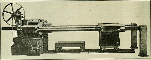
ct. The operation of this systemlightens the work and tends to make it significantly much more easy and favorablefor the workmen handling material, thereby decreasing laborturnover and increasing the efficiency of unskilled labor.The method is being manufactured and sold by the WhitingCorporation, Harvey, 111. Special Hydraulic Driving Wheel Press THE Hydraulic Press Manufacturing Company, MountGilead, Ohio, designed and constructed the unique hydraulicpress, illustrated, which was not too long ago sold by the Mc-Carter Cooper Company, New York, to the Compagnie Gen-eral De Chemins De Fer &amp Tramways en Chine, Pekin,China. This press is utilized for forcing driving wheels on or off between strain bars is 84 in. and in between ram and resistancehead is 108 in. maximum. This may be decreased to 78 in.by moving the resistance head, which is mounted on wheels.The press is also equipped with a belt-driven energy attach-ment and three plunger pump with each low and high pres-positive plungers. The pump is equipped with hand and pres-

Text Appearing Soon after Image:
Hydraulic Press for Applying Driving Wheels to Crank Axles the crank-axles of locomotives, a special style of press beingnecessary due to the fact of the crank throws. The press will manage wheels 80 in. in diameter and significantly less,becoming capable of exerting a force of 330 tons. The distance certain knock-outs whereby any one particular or all pump cylinders perhaps eliminated from service at will or automatically when themaximum pressure is reached. A little hydraulic cylinderand ram returns the main ram to its beginning position. Railway

Note About Photos
Please note that these pictures are extracted from scanned page photos that may have been digitally enhanced for readability – coloration and appearance of these illustrations may not perfectly resemble the original perform.

Good China Prototype images

Good China Prototype images

Some cool china prototype pictures:

Cesar HARADA & Protei on SCMP
china prototype
Image by cesarharada.com
protei.org
scoutbots.com

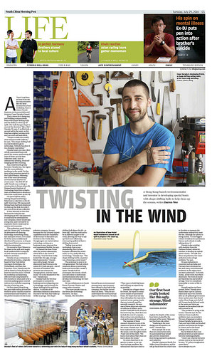
Yuen Extended farm an hour from the sea might not appear like the best place for a boat workshop, but it is exactly where French- Japanese environmentalist and inventor Cesar Harada is based.
That’s exactly where he is designing and constructing unique robotic boats with shape-shifting hulls and the capacity to clean up oil spills. The hull alterations shape to manage the path “like a fish”, Harada, 30, says. It is efficiently a second sail in the water, so the boat has a tighter turning circle and can even sail backwards.
“I hope to make the world’s most manoeuvrable sailboat,” he says. “The shape-shifting hull is a genuine breakthrough in technologies. Nobody has carried out it in a dynamic way before.”
Harada hopes 1 day a fleet of fully automated boats will patrol the oceans, performing all sorts of clean-up and information- collection tasks, such as radioactivity sensing, coral reef imaging and fish counting.
Asia could benefit greatly simply because, Harada says, the area has the worst pollution problems in the world. Yet the story of his invention started in the Gulf of Mexico, following one of the most devastating environmental disasters in current years – the 2010 BP oil spill. Harada was working in building in Kenya when the Massachusetts Institute of Technology hired him to lead a team of researchers to create a robot that could clean up the oil.
He spent half his salary going to the gulf and hiring a fisherman to take him to the oil spill. Much more than 700 repurposed fishing boats had been deployed to clean up the slick, but only 3 per cent of the oil was collected.
It then dawned on him that since the robot he was creating at MIT was patented, it could only be created by one business, which would take a long time, and it would be so high-priced that it could only be utilised in wealthy nations.
This realisation created Harada quit his “dream job” to develop an alternative oil-cleaning technologies: anything low cost, fast and open-source, so it could be freely used, modified and distributed by anyone, as long as they shared their improvements with the neighborhood.
He moved to New Orleans to be closer to the spill, and taught nearby residents how to map the oil with cameras attached to balloons and kites.
Harada set up a business to develop his invention, originally primarily based in New York before moving to Rotterdam, the Netherlands, and then San Francisco. Now, Harada says he will be based in Hong Kong for at least the subsequent 5 years. He built his workshop and adjoining office in Yuen Long himself in 5 months on what employed to be a concrete parking space covered with an iron roof right after acquiring the internet site in June last year.
He 1st visited Hong Kong last year while sailing around the planet on a four-month cruise for entrepreneurs and students. It is the ideal place for his ocean

robotics company, he says, simply because the city’s import-export capabilities and the availability of electronics in Shenzhen are the best in the globe. Also, Hongkongers are excited about technology, setting up a organization is effortless, taxes are low and regulations flexible, he says.
He named the boat Protei right after the proteus salamander, which lives in the caves of Slovenia. “Our very first boat actually looked like this ugly, strange, blind salamander,” Harada
says with a laugh. He later discovered that Proteus is the nameofaGreekseagod–oneof the sons of Poseidon, who protects sea creatures by changing form, and the name stuck. “He is the shepherd of the sea,” Harada says.
Harada constructed the very first 4 prototypes in a month by hacking and reconfiguring toys in his garage, and invented the shape-shifting hull to pull long objects. A cylinder of oil- absorbent material is attached to the end of the boat that soaks up oil like a sponge. The shape-
shifting hull permits the jib – or front sail – and the primary sail to be at distinct angles to the wind, enabling the boat to sail upwind much more efficiently, intercepting spilled oil that is drifting downwind.
“Sailing is an ancient technologies that we are abandoning. But it’s how humans colonised the whole earth, so it is a actually effective technology,” Harada says. “The shape-shifting hull is a superior way of steering a wind vessel.”
The prototype is now in its 11th generation. The hull, which measures about a metre lengthy, looks and moves like a snake’s spine. Harada built ten prototypes this month, which are sold on the internet to individuals and institutions who want to develop the technology for their personal uses.
He has collaborators in South Korea, Norway, Mexico and many other nations.
“The much more folks copy us, the greater the technology becomes,” he says.
Harada, who describes himself as an environmental entrepreneur, says investors have offered to purchase half of the organization, but he has turned them all down. “They do not realize the environmental aspect of the company,” he says.
“They want to build massive boats and sell them as expensively as feasible.”
Harada has a larger vision for Protei. He wants to create
a new market place of automated boats. He hopes that a single day they will replace the expensive, manned ocean-going vessels that are at the moment employed for scientific research. He says
1 of these ships can expense tens of millions of dollars, and a additional US,000 worth of fuel is burned each day. That does not contain the price of a captain, three or 4 crew members, a cook and a team of researchers.
The expense of these analysis missions is one of the causes we know so little about the ocean, Harada says. We have explored only five per cent of the ocean, even even though it covers 70 per cent of the earth. “We know more about Mars than we know about the ocean.”
He notes that there is no gravity in space, so we can send up huge satellites. But submarines that have attempted to discover the depths of the ocean have been crushed by the stress of the water. Ships are not totally free from risk, either.
“Seafaring is the most dangerous occupation on earth,” Harada says.
Far more folks die at sea
than on building internet sites.
An automated boat would
also prevent researchers
from becoming exposed to pollution and radiation.
Harada’s Japanese family members live 100km from Fukushima, and he will go back there for a third time
in October to measure the underwater radioactivity close to the internet site. Though he admits to getting scared, “it’s the greatest release of radioactive particles in history and nobody is actually talking about it”.
Harada is also functioning with students from the Harbour School, exactly where he teaches, to create an optical plastic sensor. “We talk a lot about air pollution, but water pollution is also a huge difficulty,” he says.
He says industries in countries such as India and Vietnam have developed so fast and many environmental problems in the region have not been addressed. “In Kerala [India], all the rivers have been destroyed. The rivers in Kochi are black like ink and smell of sewage. Now it’s fully not possible to swim or fish in them.”
Hong Kong has not been spared, either. Harada joins beach clean-ups on Lamma Island and says even months soon after an oil spill and government clean-up last year, they found crabs whose lungs had been complete of oil. He says locals fish and swim in the water and there are mussels on the seabed that are still covered in oil.
“The dilemma is as big as the ocean,” Harada says. But he believes if man created the difficulty, man can remedy it. The son of Japanese sculptor Tetsuo Harada, he grew up in Paris and Saint Malo and studied product and interactive design in France and at the Royal College of Art in London.
But he believes that at an sophisticated level, art and science grow to be indistinguishable.
“I do not see a barrier between science and art at the leading level,” he says. “It’s exactly where imagination meets details.” darren.wee@scmp.com

Good Precision Parts Engineering photos

Good Precision Parts Engineering photos

Some cool precision components engineering pictures:

Image from web page 196 of “Railway mechanical engineer” (1916)
precision parts engineering
Image by Web Archive Book Pictures
Identifier: railwaymechanica94newy
Title: Railway mechanical engineer
Year: 1916 (1910s)
Authors:
Subjects: Railroad engineering Engineering Railroads Railroad automobiles
Publisher: New York, N.Y. : Simmons-Boardman Pub. Co
Contributing Library: Carnegie Library of Pittsburgh
Digitizing Sponsor: Lyrasis Members and Sloan Foundation

View Book Web page: Book Viewer
About This Book: Catalog Entry
View All Pictures: All Photos From Book

Click here to view book on the web to see this illustration in context in a browseable on-line version of this book.

Text Appearing Before Image:
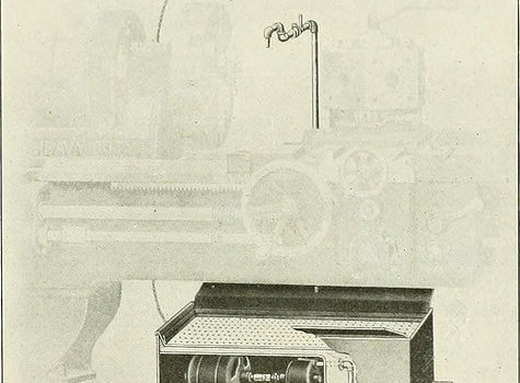
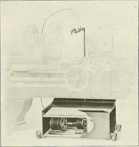
be speedily applied to anymachine tool in the shop. Several machine shop tools arenot equipped with a pan and pump, due to the fact they are usedmostly for functioning on grey iron, but sometimes the ma-chine might be used on malleable iron or steel, in which casea coolant is important for the greatest benefits. In such instances, theportable unit illustrated can be utilized to great advantage.It may also be used on machines currently provided with acoolant program, which for some cause or other is out oforder. In this emergency the transportable method shown can be instantly brought into location and production will notbe interrupted. The Fulllo pump illustrated is a total, self-containedsystem, requiring practically nothing but attaching the motor cord tothe lump socket. The total height from the floor is only14 in., which pennits its being rolled below any ordinarylathe, as shown in the illustration. Provision is produced forattaching further splash boards when essential. Thepump and motor are totally covered, as a result affording

Text Appearing Right after Image:
Fulflo Portable Lubricating Unit Utilized with Turret Lathe ample protection from each liquids and dust. The outfitcan be utilized on grinding machines as w-ell as on lathes,milling machines, drill presses, gear cutters, and so forth. Thereis only one particular moving part in the pump namely, the impeller,which has no metal contact, and for that reason cannot wear outquickly. It is packed with metallic packing which willnot reduce the shaft. The bearings are nicely lubricated, andsince the shaft is hardened and ground, extended, continuedservice may be anticipated. MULTI GRADUATED PRECISION GRINDER It has Ijeen tough in the past to machine screw threadsurfaces with the same accuracy obtained in machiningcylindrical, flat or spherical surfaces. On account of thisfact, it has been difficult to make master thread gages and themachine illustrated was created for this goal by thePrecision &amp Thread Grinder Manufacturing Company, Phil-adelphia, Pa. It can be employed in conjunction with anymachine tool and is adaptable to a selection

Note About Pictures
Please note that these photos are extracted from scanned web page pictures that may possibly have been digitally enhanced for readability – coloration and look of these illustrations could not perfectly resemble the original work.

Steven F. Udvar-Hazy Center: North American P-51C, “Excalibur III”, with tails of Concorde & Boeing 707 in background
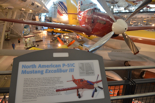
precision parts engineering
Image by Chris Devers
Quoting Smithsonian National Air and Space Museum | North American P-51C, &quotExcalibur III&quot:

On Could 29, 1951, Capt. Charles F. Blair flew Excalibur III from Norway across the North Pole to Alaska in a record-setting 10½ hours. Making use of a method of meticulously plotted &quotsun lines&quot he created, Blair was in a position to navigate with precision exactly where conventional magnetic compasses usually failed. 4 months earlier, he had flown Excalibur III from New York to London in significantly less than eight hours, breaking the existing mark by over an hour.

Excalibur III very first belonged to famed aviator A. Paul Mantz, who added added fuel tanks for long-distance racing to this normal P-51C fighter. With it Mantz won the 1946 and 1947 Bendix air race and set a transcontinental speed record in 1947 when the airplane was named Blaze of Noon. Blair bought it from Mantz in 1949 and renamed it Excalibur III, following the Sikorsky VS-44 flying boat he flew for American Export Airlines.

Present of Pan American Planet Airways

Manufacturer:
North American Aircraft Firm

Date:
1944

Nation of Origin:
United States of America

Dimensions:
Wingspan: 11.three m (37 ft)
Length: 9.eight m (32 ft three in)
Height: three.9 m (12 ft ten in)
Weight, empty: 4,445 kg (9,800 lb)
Weight, gross: 5,052 kg (11,800 lb)
Leading speed: 700 km/h (435 mph)

Supplies:
Overall: Aluminum

Physical Description:
Single seat, single engine, low wing monoplane, Planet War II fighter modified for racing.

• • • • •

Quoting Smithsonian National Air and Space Museum | Boeing 367-80 Jet Transport:

On July 15, 1954, a graceful, swept-winged aircraft, bedecked in brown and yellow paint and powered by four revolutionary new engines 1st took to the sky above Seattle. Built by the Boeing Aircraft Company, the 367-80, greater recognized as the Dash 80, would come to revolutionize industrial air transportation when its created version entered service as the renowned Boeing 707, America’s 1st jet airliner.

In the early 1950s, Boeing had begun to study the possibility of creating a jet-powered military transport and tanker to complement the new generation of Boeing jet bombers entering service with the U.S. Air Force. When the Air Force showed no interest, Boeing invested million of its personal capital to build a prototype jet transport in a daring gamble that the airlines and the Air Force would buy it after the aircraft had flown and verified itself. As Boeing had accomplished with the B-17, it risked the company on 1 roll of the dice and won.

Boeing engineers had initially primarily based the jet transport on research of improved designs of the Model 367, better identified to the public as the C-97 piston-engined transport and aerial tanker. By the time Boeing progressed to the 80th iteration, the design and style bore no resemblance to the C-97 but, for security reasons, Boeing decided to let the jet project be identified as the 367-80.

Operate proceeded swiftly right after the formal start off of the project on May possibly 20, 1952. The 367-80 mated a huge cabin primarily based on the dimensions of the C-97 with the 35-degree swept-wing design primarily based on the wings of the B-47 and B-52 but considerably stiffer and incorporating a pronounced dihedral. The wings had been mounted low on the fuselage and incorporated higher-speed and low-speed ailerons as effectively as a sophisticated flap and spoiler technique. 4 Pratt &amp Whitney JT3 turbojet engines, every producing 10,000 pounds of thrust, have been mounted on struts beneath the wings.

Upon the Dash 80’s initial flight on July 15, 1954, (the 34th anniversary of the founding of the Boeing Firm) Boeing clearly had a winner. Flying 100 miles per hour quicker than the de Havilland Comet and considerably bigger, the new Boeing had a maximum variety of much more than 3,500 miles. As hoped, the Air Force bought 29 examples of the design as a tanker/transport after they convinced Boeing to widen the design by 12 inches. Satisfied, the Air Force designated it the KC-135A. A total of 732 KC-135s were constructed.

Quickly Boeing turned its attention to promoting the airline industry on this new jet transport. Clearly the sector was impressed with the capabilities of the prototype 707 but never ever far more so than at the Gold Cup hydroplane races held on Lake Washington in Seattle, in August 1955. In the course of the festivities surrounding this occasion, Boeing had gathered a lot of airline representatives to appreciate the competitors and witness a fly past of the new Dash 80. To the audience’s intense delight and Boeing’s profound shock, test pilot Alvin &quotTex&quot Johnston barrel-rolled the Dash 80 over the lake in full view of thousands of astonished spectators. Johnston vividly displayed the superior strength and overall performance of this new jet, readily convincing the airline sector to get this new airliner.

In searching for a market, Boeing discovered a prepared consumer in Pan American Airway’s president Juan Trippe. Trippe had been spending a lot of his time looking for a appropriate jet airliner to allow his pioneering business to sustain its leadership in international air travel. Working with Boeing, Trippe overcame Boeing’s resistance to widening the Dash-80 design and style, now recognized as the 707, to seat six passengers in every single seat row rather than 5. Trippe did so by placing an order with Boeing for 20 707s but also ordering 25 of Douglas’s competing DC-8, which had but to fly but could accommodate six-abreast seating. At Pan Am’s insistence, the 707 was produced four inches wider than the Dash 80 so that it could carry 160 passengers six-abreast. The wider fuselage created for the 707 became the regular style for all of Boeing’s subsequent narrow-body airliners.

Though the British de Havilland D.H. 106 Comet and the Soviet Tupolev Tu-104 entered service earlier, the Boeing 707 and Douglas DC-8 were larger, more quickly, had higher range, and had been far more lucrative to fly. In October 1958 Pan American ushered the jet age into the United States when it opened international service with the Boeing 707 in October 1958. National Airlines inaugurated domestic jet service two months later using a 707-120 borrowed from Pan Am. American Airlines flew the initial domestic 707 jet service with its personal aircraft in January 1959. American set a new speed mark when it opened the first often-scheduled transcontinental jet service in 1959. Subsequent nonstop flights amongst New York and San Francisco took only 5 hours – three hours much less than by the piston-engine DC-7. The a single-way fare, such as a surcharge for jet service, was five.50, or 1 round trip. The flight was nearly 40 percent more rapidly and virtually 25 percent more affordable than flying by piston-engine airliners. The consequent surge of targeted traffic demand was substantial.

The 707 was originally designed for transcontinental or a single-cease transatlantic variety. But modified with further fuel tanks and more efficient turbofan engines, the 707-300 Intercontinental series aircraft could fly nonstop across the Atlantic with full payload below any situations. Boeing constructed 855 707s, of which 725 were bought by airlines worldwide.

Having launched the Boeing Company into the commercial jet age, the Dash 80 soldiered on as a highly effective experimental aircraft. Till its retirement in 1972, the Dash 80 tested numerous advanced systems, many of which have been incorporated into later generations of jet transports. At one point, the Dash 80 carried three distinct engine kinds in its four nacelles. Serving as a test bed for the new 727, the Dash 80 was briefly equipped with a fifth engine mounted on the rear fuselage. Engineers also modified the wing in planform and contour to study the effects of diverse airfoil shapes. Many flap configurations were also fitted which includes a highly sophisticated method of &quotblown&quot flaps which redirected engine exhaust over the flaps to increase lift at low speeds. Fin height and horizontal stabilizer width was later improved and at one particular point, a special a number of wheel low stress landing gear was fitted to test the feasibility of operating future heavy military transports from unprepared landing fields.

After a extended and distinguished profession, the Boeing 367-80 was finally retired and donated to the Smithsonian in 1972. At present, the aircraft is installated at the National Air and Space Museum’s new facility at Washington Dulles International Airport.

Present of the Boeing Company

Manufacturer:
Boeing Aircraft Co.

Date:
1954

Nation of Origin:
United States of America

Dimensions:
Height 19′ 2&quot: Length 73′ ten&quot: Wing Span 129′ eight&quot: Weight 33,279 lbs.

Physical Description:
Prototype Boeing 707 yellow and brown.

• • • • •

Quoting Smithsonian National Air and Space Museum | Concorde, Fox Alpha, Air France:

The initial supersonic airliner to enter service, the Concorde flew thousands of passengers across the Atlantic at twice the speed of sound for more than 25 years. Developed and built by Aérospatiale of France and the British Aviation Corporation, the graceful Concorde was a stunning technological achievement that could not overcome serious financial troubles.

In 1976 Air France and British Airways jointly inaugurated Concorde service to destinations about the globe. Carrying up to 100 passengers in excellent comfort, the Concorde catered to 1st class passengers for whom speed was vital. It could cross the Atlantic in fewer than four hours – half the time of a traditional jet airliner. Even so its higher operating charges resulted in really higher fares that restricted the number of passengers who could afford to fly it. These problems and a shrinking industry at some point forced the reduction of service till all Concordes were retired in 2003.

In 1989, Air France signed a letter of agreement to donate a Concorde to the National Air and Space Museum upon the aircraft’s retirement. On June 12, 2003, Air France honored that agreement, donating Concorde F-BVFA to the Museum upon the completion of its last flight. This aircraft was the 1st Air France Concorde to open service to Rio de Janeiro, Washington, D.C., and New York and had flown 17,824 hours.

Present of Air France.

Manufacturer:
Societe Nationale Industrielle Aerospatiale
British Aircraft Corporation

Dimensions:
Wingspan: 25.56 m (83 ft 10 in)
Length: 61.66 m (202 ft 3 in)
Height: 11.3 m (37 ft 1 in)
Weight, empty: 79,265 kg (174,750 lb)
Weight, gross: 181,435 kg (400,000 lb)
Leading speed: 2,179 km/h (1350 mph)
Engine: 4 Rolls-Royce/SNECMA Olympus 593 Mk 602, 17,259 kg (38,050 lb) thrust every
Manufacturer: Société Nationale Industrielle Aérospatiale, Paris, France, and British Aircraft Corporation, London, United Kingdom

Physical Description:
Aircaft Serial Number: 205. Such as four (4) engines, bearing respectively the serial quantity: CBE066, CBE062, CBE086 and CBE085.
Also included, aircraft plaque: &quotAIR FRANCE Lorsque viendra le jour d’exposer Concorde dans un musee, la Smithsonian Institution a dores et deja choisi, pour le Musee de l’Air et de l’Espace de Washington, un appariel portant le couleurs d’Air France.&quot

Good Precision Engineering Services images

Good Precision Engineering Services images

Verify out these precision engineering services pictures:

Red Arrows
precision engineering services
Image by afaloon
Airbourne is proud to welcome back the RAF Aerobatic Group, the Red Arrows, a single of the world’s premier aerobatic show teams. 2014 marks a unique year for the team who will be celebrating their 50th show season.

With a trademark combination of close formations and precision flying, the Red Arrows have been displaying considering that 1965 and is made up of a team of 120 men and women including pilots, engineers and support employees. They represent the speed, agility and precision of the Royal Air Force and the public face of the service, assist in recruiting to the Armed Forces and act as ambassadors for the United Kingdom promoting the very best of British.

A lot of of the current pilots were first inspired to pursue a career in the military and join the Royal Air Force following watching the Team in the sky as children.

To apply for selection to the Red Arrows, pilots must:
* Have at least 1,500 quick jet flying hours
* Have completed a frontline tour
* Be assessed as above average in their flying role

The Red Arrows are renowned for the visual impact of their red, white and blue smoke trails. Smoke also plays an critical flight security function also allowing the pilots to judge wind speed and direction – enabling them to locate other aircraft when distinct sections of the Team’s formations are several miles apart.

Aircraft Specifications

Dimensions
Height: 4m
Length: 11.85m
Wingspan: 9.39m

Overall performance
Maximum speed: 622mph

Powerplant
Rolls-Royce Turbomeca Adour Mk 861 turbofan

Lumps of Clay – excerpt thumbnail
precision engineering services
Image by andrewtoskin
a photo comic

words by Andrew Toskin writing as Niccolo Florence

photography by hikaru starr

People have been worrying as well significantly about ebola. How lengthy until you catch children?

Copyright 2014. This function is published beneath a Inventive Commons Attribution-NonCommercial-ShareAlike 4. International License. Which means fundamentally that you’re cost-free to copy and share this operate — provided you credit us as the supply — but not sell it. We are open to the thought of enabling commercial use, even though just ask us 1st. Reposts and remixes of this work should attribute Niccolo Florence and hikaru starr, and hyperlink to curefornightmares.com

Text and images were composited with GIMP. Complete-size JPEGs are here on Flickr.
You’ll also discover the present supply files, plus various exported file formats at
the Net Archive.

Here’s the original comic script:

Panel 1: HIK_4769 edit.JPG — silhouetted loved ones on the
beach, with pier and sunset.

@Title and Byline
&gt Lumps of Clay
words by Niccolo Florence
photography by hikaru starr
curefornightmares.com

caption: I am no one’s father. (However?)

Panel two: IMG_0587.jpg — intense close-up on infant Ema’s face.

caption: But unless or until I succumb, it is my duty
to warn you that *children are harmful.* Stay away
from them anytime feasible.

Panel 3: img_0811.jpg — Ema in a green hoodie in front of
one hundred dangling wooden placards.

caption: If you hear any friends or sexual partners talk about
how their “biological clocks are ticking,” leave the region
and wash your hands. If they *bring* any youngsters with them,
immediately evacuate all childless adults from the vicinity
and notify the nearby authorities.

Panel four: IMG_8976.jpg — Ema peeking around the bole of a
tree, with a creepy statue in the background.

caption: Most individuals are aware of the troubles young children
can trigger, but numerous do not realize the complete extent
of the danger, and so do not take sufficient
precautions. Fortunately, young children do come with a number
of warning indicators to ward off potential adult
caretakers.

Panel five: img_0276 roppongi edit.jpg — Ema’s face covered in red paint(?)

caption: Some of the better known examples consist of the
smells and noise…

Panel 6: HIK_1878.jpg — Ema standing on leading of a statue,
looking down at us.

caption: Less apparent issues: They are also
codependent, irrational, evil creatures, unable to
negotiate or delay gratification. Any individual who shares a
household with a child for extended will slave their days
away to slake ever-altering whims.

Panel 7: IMG_0452.jpg — Ema with a blue onesie more than her
head. Possibly the cutest in the set.

caption: Kids are precision engineered to brainwash
you into loving them.

Panel 8: DSC_4229.jpg — Ema operating to a seesaw in a park.

caption: They will break your things, and break the
bank, and break your dreams, but absolutely nothing is worse than
the techniques they break your heart.

Panel 9: HIK_4865.jpg — Ema seen through a kaleidoscope.

caption: Youngsters are the most insidious of parasites:
The longer they remain with you, the deeper their
tendrils grow into you, cinching your ribs tighter and
tighter around your lungs, slithering into your
nervous technique until you can scarcely believe about
anything else — and then they develop up and leave you.

Panel ten: HIK_0131.jpg — Ema at a shrine, pouring water
over one hand.

caption: And the hole they leave behind just bleeds and
bleeds…

Panel 11: HIK_9941.jpg — Ema wearing an auburn wig.

caption: This is the worst element of all, something that
even most in-individuals who have tested constructive for
children may not recognize for years.

Panel 12: HIK_9841.jpg — black and white Ema holding her
hand up to block the camera.

caption: Since you and your child will drive each
other crazy. *Someone’s* life is receiving ruined, and
you will be terrified that it will not be yours.

caption: You will get in a stupid fight about producing the bed or
some thing and you will both commence screaming and throwing
items, and next thing you know it hits me that I’m
becoming my mother, I’m perpetuating the cycle.

Panel 13: HIK_9310.jpg — Sick Ema in jacket and face mask.

caption: Kids are so fragile, so malleable. Soft
lumps of clay that mold to the contours of your hand
no matter how you try *not* to mold them.

caption: Right after all my blunders, will she be okay? Will
she grow up all proper?

Panel 14: IMG_0567.jpg — singer with guitar and mic.

caption: Could the way she sings in the bathroom be a
sign that she’ll grow up to be a musician?

Panel 15: IMG_8976.JPG — A dancer.

caption: A dancer?

Panel 16: _HIK8727_014-two.jpg — model leaning over glass and handrail.

Panel 17: HIK_5078 raw edit.JPG — kabuki(?) performer on stage.

caption: Some kind of artist, surely.

Panel 18: HIK_1095.jpg — Ema, facing away from the camera.

caption: …Will she be happy?

Panel 19: Huge, complete-page shot. HIK_5285.JPG — Mysterious portrait of Ema
in a hat and daisy dress at night, hunting straight into the camera.

caption: …She isn’t even my daughter. I’ve only met
her once. But I currently enjoy her so much it hurts. I
worry obtaining a youngster of my own would *destroy* me.

End.

Good Mechanical Engineering China pictures

Good Mechanical Engineering China pictures

Some cool mechanical engineering china pictures:

Image from web page 182 of “An American engineer in China” (1900)
mechanical engineering china
Image by World wide web Archive Book Images
Identifier: cu31924023226081
Title: An American engineer in China
Year: 1900 (1900s)
Authors: Parsons, William Barclay, 1859-1932
Subjects: Parsons, William Barclay, 1859-1932 Railroads
Publisher: New York, McClure, Phillips &amp co.
Contributing Library: Cornell University Library
Digitizing Sponsor: MSN

View Book Web page: Book Viewer
About This Book: Catalog Entry
View All Pictures: All Images From Book

Click here to view book on the web to see this illustration in context in a browseable on the internet version of this book.

Text Appearing Before Image:
ame on the base, they would beconsidered of Chinese make. They are inex-pensive, of the sort preferred by the Chinaman,although perhaps not for sale in Hamburg orBerlin. On the other hand, the American article,considerably more handsome, from our point of view,but also a lot more high-priced, is of the exact same style as issold on Broadway in New York. There is no want to multiply examples. Thereawaits the American manufacturer an outlet, espe-cially for tools, machinery, and other articles iniron and steel. He will find a demand for thesmaller and lighter machines, rather than for thelarger ones. That is to say, he must appeal firstto the person worker who exists now, ratherthan aim at the needs of a conglomeration in afactory which will come about in the future. The Chapter V: Industrial Relations 177 totals should be basic in character, casil WMirketlami kept in ortler, ami without tlie applicationof fast-return and other mechanical devices s&lttnecessary lor labor-saviiicr with us. Litiht W(jod-

Text Appearing Soon after Image:
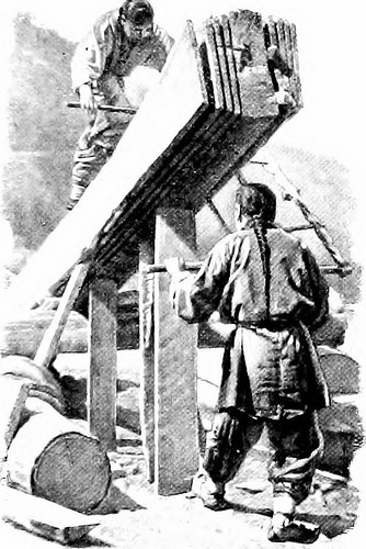
A Chinese Saw-mill The teeth of the saw are arranged to reduce on the up stroke alternatively oton the down, as in other countries operating machiner} can be made to supplant thepresent manual-labnr techniques and a laroe fieldis open for all sorts oi pumps, windmills, piping-,and other articles of Inrlraulic machinerv. Cott(jn g(jods of the finer grades, as properly as the 178 An American Engineer in China coarser which are supplied, household articles ofall kinds, glassware, window-glass, wall-paper,and plumbing fixtures will find a prepared market,as will also farm equipments, such as light-wheeledvehicles and small agricultural implements of allkinds. In these, as in a lot of manufactured arti-cles, American trade has as yet made little or noimpression and yet the American post has anacknowledged superiority over any other for-eign make. It is essential for us also to study the China-man himself. The English and American tradersmake but small try to find out the language, andtherefore frequently f

Note About Pictures
Please note that these images are extracted from scanned web page images that might have been digitally enhanced for readability – coloration and appearance of these illustrations may possibly not perfectly resemble the original function.

Image from web page 124 of “American engineer and railroad journal” (1893)
mechanical engineering china
Image by Internet Archive Book Images
Identifier: americanengineer77newy
Title: American engineer and railroad journal
Year: 1893 (1890s)
Authors:
Subjects: Railroad engineering Engineering Railroads Railroad automobiles
Publisher: New York : M.N. Forney
Contributing Library: Carnegie Library of Pittsburgh
Digitizing Sponsor: Lyrasis Members and Sloan Foundation

View Book Page: Book Viewer
About This Book: Catalog Entry
View All Images: All Photos From Book

Click right here to view book on-line to see this illustration in context in a browseable online version of this book.

Text Appearing Before Image:
co, the firststop to be at Honolulu. From there he goes to Japan, Koreaand Slam, and from China he will travel more than the Trans-Siberian Railroad to Russia. He plans to go to every countryin Europe. Mr. Gross will be absent from this nation abouta year. The goal of his trip is to make a careful investi-gation of the opportunities for American locomotives in theOrient and European nations and to establish systematicbusiness relations. Mr. Gross will be accompanied on his tripby Cliarles M. Muchnic, till recently mechanical engineer ofthe Denver &amp Rio Grande, who will act as Mr. Gross secretary. Mr. Max Toltz has resigned as mechanical engineer of theGreat Northern Railway. He is engaged in superintendingthe application of his system of acetylene car lighting to alarge quantity of vehicles on the Canadian Pacific, and has beenretained by that road in a consulting engineering capacity inconnection with the new shops at Montreal. March, 1903. AMERICAN ENGINEER AND RAILROAD JOURNAL. Ill

Text Appearing After Image:
nniDD DD

Note About Pictures
Please note that these images are extracted from scanned page images that may have been digitally enhanced for readability – coloration and look of these illustrations could not completely resemble the original operate.

110824-N-XR557-038
mechanical engineering china
Image by Cooperation Afloat Readiness and Coaching (CARAT)
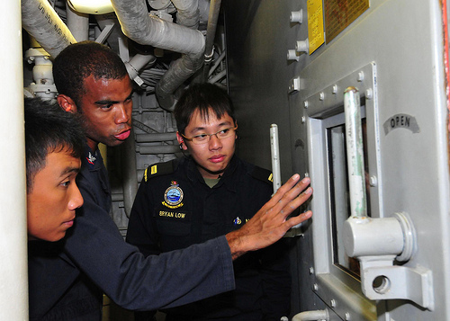
110824-N-XR557-038 SOUTH CHINA SEA (Aug. 24, 2011) Gas Turbine Systems Technician (Mechanical) 3rd Class Earl Bellamy, center, of the guided missile destroyer USS Chung-Hoon (DDG 93) shows Republic of Singapore Navy officers 2nd Lt. Dominic Lew, left, and Lt. Bryan Low, right, the propulsion gas turbine module during a tour of the engineering spaces whilst underway for Cooperation Afloat Readiness and Training (CARAT) Singapore 2011. CARAT 2011 is a series of bilateral workout routines held annually in Southeast Asia to strengthen relationships and boost force readiness. (U.S. Navy photo by Mass Communication Specialist 2nd Class Katerine Noll/Released)

Good Prototype Companies In China pictures

Good Prototype Companies In China pictures

Some cool prototype producers in china pictures:

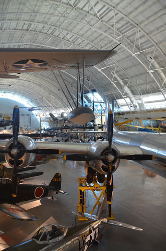
Steven F. Udvar-Hazy Center: south hangar panorama, including Vought OS2U-3 Kingfisher seaplane, B-29 Superfortress “Enola Gay”, amongst other folks
prototype manufacturers in china
Image by Chris Devers
Quoting Smithsonian National Air and Space Museum | Vought OS2U-3 Kingfisher:

The Kingfisher was the U.S. Navy’s main ship-based, scout and observation aircraft throughout Planet War II. Revolutionary spot welding strategies gave it a smooth, non-buckling fuselage structure. Deflector plate flaps that hung from the wing’s trailing edge and spoiler-augmented ailerons functioned like further flaps to enable slower landing speeds. Most OS2Us operated in the Pacific, exactly where they rescued several downed airmen, including Globe War I ace Eddie Rickenbacker and the crew of his B-17 Flying Fortress.

In March 1942, this airplane was assigned to the battleship USS Indiana. It later underwent a six-month overhaul in California, returned to Pearl Harbor, and rejoined the Indiana in March 1944. Lt. j.g. Rollin M. Batten Jr. was awarded the Navy Cross for creating a daring rescue in this airplane beneath heavy enemy fire on July four, 1944.

Transferred from the United States Navy.

Manufacturer:
Vought-Sikorsky Aircraft Division

Date:
1937

Country of Origin:
United States of America

Dimensions:
General: 15ft 1 1/8in. x 33ft 9 1/2in., 4122.6lb., 36ft 1 1/16in. (460 x 1030cm, 1870kg, 1100cm)

Components:
Wings covered with fabric aft of the major spar

Physical Description:
Two-seat monoplane, deflector plate flaps hung from the trailing edge of the wing, ailerons drooped at low airspeeds to function like further flaps, spoilers.

• • • • •

Quoting Smithsonian National Air and Space Museum | Boeing B-29 Superfortress &quotEnola Gay&quot:

Boeing’s B-29 Superfortress was the most sophisticated propeller-driven bomber of Planet War II and the very first bomber to house its crew in pressurized compartments. Despite the fact that designed to fight in the European theater, the B-29 located its niche on the other side of the globe. In the Pacific, B-29s delivered a selection of aerial weapons: standard bombs, incendiary bombs, mines, and two nuclear weapons.

On August 6, 1945, this Martin-constructed B-29-45-MO dropped the very first atomic weapon used in combat on Hiroshima, Japan. 3 days later, Bockscar (on display at the U.S. Air Force Museum near Dayton, Ohio) dropped a second atomic bomb on Nagasaki, Japan. Enola Gay flew as the advance climate reconnaissance aircraft that day. A third B-29, The Fantastic Artiste, flew as an observation aircraft on each missions.

Transferred from the United States Air Force.

Manufacturer:
Boeing Aircraft Co.
Martin Co., Omaha, Nebr.

Date:
1945

Country of Origin:
United States of America

Dimensions:
General: 900 x 3020cm, 32580kg, 4300cm (29ft six five/16in. x 99ft 1in., 71825.9lb., 141ft 15/16in.)

Components:
Polished all round aluminum finish

Physical Description:
4-engine heavy bomber with semi-monoqoque fuselage and high-aspect ratio wings. Polished aluminum finish all round, normal late-World War II Army Air Forces insignia on wings and aft fuselage and serial number on vertical fin 509th Composite Group markings painted in black &quotEnola Gay&quot in black, block letters on reduce left nose.

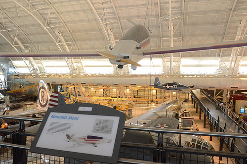
Steven F. Udvar-Hazy Center: Monnett Moni stunt plane, hanging more than the B-29 Enola Gay
prototype manufacturers in china
Image by Chris Devers
Quoting Smithsonian National Air and Space Museum | Monnett Moni:

Schoolteacher John Monnett designed the Moni (mo-nee) throughout the early 1980s, and then coined the term ‘air recreation vehicle’ to describe this airplane. Monnett’s style nearly captured all the merits that so a lot of leisure pilots longed to uncover in one particular aircraft. The Moni looked excellent just sitting on the ramp. It performed properly, and an individual reasonably handy with typical shop tools could construct one particular in their personal garage. The style had considerably going for it, but like so a lot of homebuilt aircraft ahead of and since, a handful of crucial engineering lapses in the style, plus problems with the engine and propeller, relegated the Moni to the category of homebuilt aircraft that guarantee considerably in style but fail to provide. Harold C. Weston generously donated his Moni to the National Air and Space Museum in April 1992. Weston built the airplane himself and flew it far more than 40 hours.

Gift of Harold C. Weston.

Designer:
John Monnett

Manufacturer:
Harold Weston

Nation of Origin:
United States of America

Dimensions:
Wingspan: 8.four m (27 ft six in)
Length: four.five m (14 ft 7.5. in)
Height: .7 m (28 in)
Weights: Gross, 227 kg (500 lb)
Empty, 118 kg (260 lb)
Engine: KFM 107E, two-cylinder, two-stroke air-cooled, 25 horsepower

Materials:
Overall – Aluminum airframe, semi-monocoque construction.

Physical Description:
Low-wing, vee-tail motorglider, beige with purple, red, and orange trim single-seat aircraft built from parts sent to builder by mail-order kit mounted on roadable trailer with wings detached (A19940029000).

Good Mechanical Engineering China photos

A few nice mechanical engineering china pictures I discovered:

Image from page 318 of “Railway mechanical engineer” (1916)
mechanical engineering china
Image by World wide web Archive Book Photos
Identifier: railwaymechanica96newy
Title: Railway mechanical engineer
Year: 1916 (1910s)
Authors:
Subjects: Railroad engineering Engineering Railroads Railroad automobiles
Publisher: New York, N.Y. : Simmons-Boardman Pub. Co
Contributing Library: Carnegie Library of Pittsburgh
Digitizing Sponsor: Lyrasis Members and Sloan Foundation

View Book Page: Book Viewer
About This Book: Catalog Entry
View All Images: All Images From Book

Click here to view book on the web to see this illustration in context in a browseable on the internet version of this book.

Text Appearing Before Image:
n referred to, the Board of Communication rec-ommended an extension to Suiyuan. This undertakingreceived imjjerial sanction in 1909 and building wascommenced in the following year. The length of the secondsection is 2J5 miles. This, as nicely as all other imi)ortantlines in China, is of the common gage, four ft. XJj in. The line runs along the west wall of Pekin and then ina northwesterly direction to Nankow, passing over the WestHills via Nankow Pass, to Kaigan and thence to Fengchcuand Suiyuan. The principal rail connections are at Fengtaiwith the Pekin-Mukden and Pekin-Hankow lines, .hout7.S per cent of the income received is from freight and thebalance from jiassenger visitors. Tlie heaviest movementsare toward Pekin and Fengtai. Fair grades were obtainedfor tlie line witli the cxcejjtion of the portion more than the WestHills, at which point there is a grade of ,S..S3 per cent,11 miles long with uncom])ensated curves (jf 600 ft. radius.ibis grade ((lUrcIs tlie nidvenuiit nf tr.iffn.

Text Appearing After Image:
Mik.ido Lor.omotlvc U»ctl on Level Section* 305 306 RAILWAY MECHANICAL ENGINEER Vol. 96, No. 6 Table of Dimensions, Weights and Proportions Cylinders, higher pressure 24 in. by 28 in. Cylinders, low pressure 38 in. by 28 in. Valves and valve setting: … , Kind and size, H.P Piston 14 in., single ported Type and size, L.P Piston 16 in., double ported Maximum travel H.P. 6A in., L.P. 6 in. Outside lap HP^ 1 in,, LP- !^ !• ExhLust clearance H.P. ■4 in., L.P. A in. Lead in complete gear H.P. H in., L.P. A in. Weights in worTv-ing order: On drivers ^S?™ r On front truck S^°2 ^ On trailing truck 29.000 b. Total engine 446,000 b. Tender 192.700 lb. Wteel base: Driving, every single engine i j &lt 11 Total engine L c Total engine and tender 85 It. six in. Wheels, diameter outdoors tires: Driving Front and trailing truck Tender Journals, diameter and length: . , ., • Driving, primary 10 .in. by 12 m. Driving, other individuals 9 in. by 12 in. Front and trailing truck 6 in. by 1-i in. Variety ^%Vn lb Steam press

Note About Pictures
Please note that these pictures are extracted from scanned page pictures that may have been digitally enhanced for readability – coloration and look of these illustrations may not completely resemble the original function.

Jianwai SOHO 24
mechanical engineering china
Image by tom$
JIAN WAI SOHO
location: Beijing, China
principal use: several dwelling, shop, workplace, sport club, preschool
site location: 122,775 sq meters
developing location: 34,823 sq meters
total floor region: 504,237 sq meters
structure: reinforced concrete, partly steel frame
quantity of stories: two basements and 31 stories
architects: Riken Yamamoto &amp Field Shop, C+A, MIKAN, Beijing New Era Architectural Design and style, Beijing Dongfang Huatai Architectural &amp Engineering
structural engineers: Plus One Structural Des. &amp Eng. Firm
mechanical engineers: Kankyo Engineering
interior designers / furniture designers: Yasuo Kondo Design
sign designers: Hiromura Design and style Office

Good China Mechanical Engineering pictures

Good China Mechanical Engineering pictures

A few good china mechanical engineering images I found:

Image from web page 161 of “Railway mechanical engineer” (1916)
china mechanical engineering
Image by Web Archive Book Images
Identifier: railwaymechanica94newy
Title: Railway mechanical engineer
Year: 1916 (1910s)
Authors:
Subjects: Railroad engineering Engineering Railroads Railroad automobiles
Publisher: New York, N.Y. : Simmons-Boardman Pub. Co
Contributing Library: Carnegie Library of Pittsburgh
Digitizing Sponsor: Lyrasis Members and Sloan Foundation

View Book Page: Book Viewer
About This Book: Catalog Entry
View All Images: All Images From Book

Click here to view book on the web to see this illustration in context in a browseable on the web version of this book.

Text Appearing Just before Image:
per cent of the coal capacity of 13,300 lb. The water capacitv of the ten-der is four,800 U. S. gallons. Excellent care was essential in making the tender design and style tomeet tlie limitations of axle load as provided in the specification.In common, the locomotive was made along the lines ofAmerican practice and the builders had been offered a cost-free handin the construction of information so lengthy as they had been kept withinthe limitations of the specifications. The common dimensionsof the locomotive, as effectively as the actual weights as comparedwith the weight limitations .specified are offered in the adhere to-ing table: Engine Actual Limit of weight weight i-ront drivers 32.600 33.000 Alain drivers 32,600 33,000 Dack drivers 32,000 33.000 Total drivers 97,200 99,000 r.ngine truck 28,400 28,500 Trailing truck 30,400 31,300 Engine, total l.io,000 158,800 Tender J ront wheel 30,400 30,800 Middle wheel 30,600 30,800 l:ack wheel 30,600 30,800 Total 91,600 92,400 General Data Cage four ft. Syi in. Service Mixed luel Soft coal

Text Appearing Right after Image:
Prairie Variety Locomotive for Service in China Static wheel load. In order to come inside these call for-ments and at the very same time offer the appropriate counterbal-ance, the reciprocating parts have been made of extremely light designand a special method was employed to secure an precise ad-justment of the counterweights in the driving wheels. Thedynamic augment requirements were met and by indicates ofcareful adjustment the suitable counterbalance was securedfor the reciprocating w^eights. The boiler is of the extended wagon top tpe, radiallystayed and fitted with a combustion chamber. The locomo-tives are equipped with superheaters and the reversing mech-anism is of the Lawson patented screw t)pe, which providesfor effortless operation and is fitted with a constructive locking de-vice and an indicator which shows the exact reduce-off at whichthe engine is operated. The tender is of the six-wheel, rigid wheel base sort, witliplate side frames, the journal boxes operating in pedestalsriveted to the outdoors plates of the

Note About Pictures
Please note that these pictures are extracted from scanned page photos that may have been digitally enhanced for readability – coloration and look of these illustrations could not perfectly resemble the original function.

Good Machining Engineering images

Good Machining Engineering images

A couple of nice machining engineering images I identified:

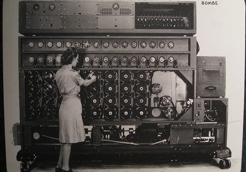
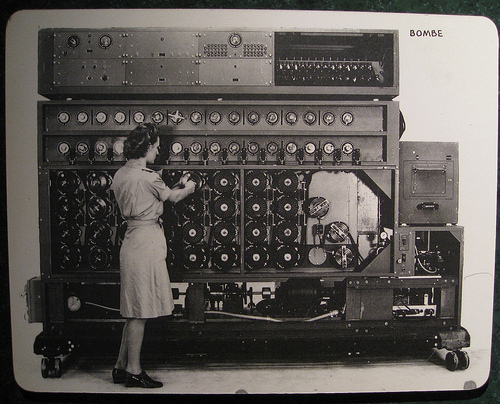
US Navy Cryptanalytic Bombe
machining engineering
Image by brewbooks
A US Navy WAVE sets the Bombe rotors prior to a run

The US NAvy cryptanalytic Bombes had only one particular purpose: Decide the rotor settings utilized on the German cipher machine ENIGMA. Initially created by Joseph Desch with the National Cash Register Firm in Dayton, Ohio, the Bombes worked mainly against the German Navy’s four-rotor ENIGMAs. Without the correct rotor settings, the messages were practically unbreakable. The Bombes took only twenty minutes to complete a run, testing the 456,976 feasible rotor settings with a single wheel order. Various Bombes attempted various wheel orders, and a single of them would have the final appropriate settings. When the a variety of U-boat settings have been identified, the Bombe could be switched over to operate on German Army and Air Force 3-rotor messages.
Supply: National Cryptologic Museum

Comment on the above
The 4 rotor program had 26^4 or 456,976 settings whilst the theree rotor technique had 26^three or 17,756 settings. It appears like the dilemma scale in a linear way as it took 50 seconds to verify 17,756 setting (~350 per second) whilst the 4 rotor resolution in 20 minutes is ~ 380 settings per second.

I also think the designer Joseph Desch sounds like a remarkable engineer that I never ever heard of just before.

Bombe on Wikipedia
As soon as the British had offered the Americans the information about the bombe and its use, the US had the National Cash Register Company manufacture a great several extra bombes, which the US then utilised to help in the code-breaking. These ran significantly quicker than the British version, so quick that as opposed to the British model, which would freeze quickly (and ring a bell) when a attainable answer was detected, the NCR model, upon detecting a feasible remedy, had to &quotremember&quot that setting and then reverse its rotors to back up to it (meanwhile the bell rang).

Source of following material : National Cryptologic Museum

Diagonal Board is the heart of the Bombe unit. Electrically, it has 26 rows and 26 columns of points, each with a diagonal wire connection. These wires connect every single letter in a column with the exact same position in each and every row. A letter cannot plug into itself these are recognized as &quotself-steckers.&quot The resulting pattern is a series of diagonal lines. The purpose of the diagonal board is to eliminate the complications brought on by the Enigma’s plugboard. Provided particular rotor settings, only specific plugboard settings can result in the proper encrypted letter. The diagonal board disproved hundreds of rotor settings, permitting for only a handful of possibly right settings to outcome in a &quotstrike&quot.

Amplifier Chassis had two purposes, very first to detect a hit and second to decide if it was useful. It supplied the tie-in from the diagonal board, the locator, and the printer circuits.

Thyratron Chassis was the machine’s memory. Considering that the wheels spun at such a high speed, they could not instantly quit rotating when a correct hit was detected. The Thyratron remembered exactly where the appropriate hit was located and indicated when the Bombe has rewound to that position. It also told the machine when it had completed a run and gave the final stop signal.

Switch Banks tell the Bombe what plain to cipher letters to search for. Utilizing menus sent to the Bombe deck by cryptanalysts, WAVES set each dial making use of unique wrenches. 00 equates to the letter A and 25 to the letter Z. The dials work together in groups of two. 1 dial is set to the plain test letter and the other to its corresponding cipher letter as determined by cryptanalysts. There are sixteen sets of switch banks, however, only fourteen had been required to comprehensive a run. As the machine worked through the rotor settings, a correct hit was possible if the electrical path in all fourteen switch banks corresponded to every of their assigned plaintext/cipher combinations.

Wheel Banks represent the 4 rotors used on the German U-boat Enigma. Every column interconnects the 4 rotors, or commutators, in that column. The leading commutator represented the fourth, or slowest, rotor on the Enigma, although the bottom wheel represented the rightmost, or fastest, rotor. The WAVES set the rotors according to the menu developed by the cryptanalysts. The 1st have been set to 00, and each set soon after that corresponded to the plain/cipher hyperlink with the crib (the assumed plain test corresponding to the cipher text.) Normally this meant that each wheel bank stepped up one spot from the 1 on its left. When the machine ran, each bottom rotor stepped forward, and the machine electrically checked to see if the assigned situations had been met. If not, as was generally the case, every bottom wheels moved 1 a lot more place forward. Nonetheless, the bottom commutator moved at 850 rpm, so it only took twenty minutes to full a run of all 456,976 positions.

Printer automatically printed the details of a attainable hit. When the Bombe determined that all the possible conditions had been met. it printed wheel order, rotor settings and plugboard connections.

Motor Manage Chassis controlled both forward and reverse motors. The Bombe was an electromechanical machine and needed a number of gauges for monitoring. It also necessary a Braking Assembly to slow the forward motion when a hit was detected and to bring the machine to a complete quit when a run was completed.

i09_0214 129

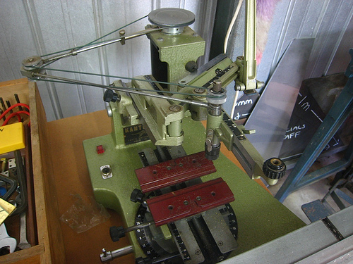
Engraving machine
machining engineering
Image by brotherlywalks