Cool Die Casting China pictures

Cool Die Casting China pictures

Some cool die casting china pictures:

“Kyle Petty” Pontiac Grand Prix
die casting china
Image by Flá Dechen
Series: Cyber Racers
Year: 1997
Cast: 1997
Model no.:
Created in China

Ford GT-90
die casting china
Image by Flá Dechen
Series: 1998 First Editions
Year: 1998
Cast: 1997
Model no.: 18850
Created in China

Ford GT-90
die casting china
Image by Flá Dechen
Series: 1998 Initial Editions
Year: 1998
Cast: 1997
Model no.: 18850
Produced in China

Use Of Wireframes, Mockups, And Prototypes In Diverse Phases Of Project

Use Of Wireframes, Mockups, And Prototypes In Diverse Phases Of Project

Website development is really skillful field in which a single has to be quite proactive on all phases of designing starting from designing to testing. Yes there are some tools which can help them during all different phases but it all rely on capabilities of designer or developer. Initial phase signifies in designing phase one particular have to perfectly comprehend client wants and requirement whereas right after that it is all depend on your consistency with which you execute your plan due to the fact there are all probabilities then you may well carried away with some other desirable functions. At the end, it all depends on look and functionality of your internet site. In all these phases there are tools like wireframes, mockups (or mockup software), and prototypes which can be utilized for nicely mannered and preplanned processes.
Designing phase:
In designing phase, wire frames can be really handy since they are drawing carried out by designer according to wants and needs of client. Client can give feedbacks about positives and negatives of designing and based one consumers feedback designer can make needed alterations and perform additional on designing. There are diverse approaches to carry out wireframes depending on size and style of website. If designer feel that project is too large and cant manage it via pen and paper then it is advisable to use application. There is specialized software program is also available along with frequent graphics computer software which can be utilized for very same goal. 1 client offers green signal to designers design it becomes all easy for both parties to go along nicely without any conflict.
Improvement phase:
In improvement phase, it is really essential to maintain going on identical track till completion of project, because there are chances that you may well go down to incorrect path. There are several reasons like communication gap, other attractive techniques to do same point, and conflicts in your team, but there a way out from this dilemma. You can use mockup software program obtainable in market place which can help you to precisely measure your progress in project. By using mockups you are ensuring to adhere to identical path during entire project. Use of this computer software can only lead you to far better output and enhanced outputs. It also support you to save time as properly as efforts you need to total any project since you are not looking anywhere else other than your own project.
Completion phase:
Look, functioning, and testing of website play key role in completion process. There are particular models of prototypes which can be used in during any phase of project. If you have used wireframes and mockups in you project then you dont have to use very first two models which are initial designing phase. Another two models can be utilized for visual look and functioning of your finish solution. In that, you have t present your internet site in defined pattern to your client and according to clientele comments you need to have to execute your next actions. This can be quite valuable in making your product excellent according to consumers requirements.

If you have utilised wireframes and Mockups in you project then you dont have to use 1st two models which are initial designing phase.

Uncover Much more China Prototypes Articles

Good Mechanical Engineering China photos

A few nice mechanical engineering china pictures I discovered:

Image from page 318 of “Railway mechanical engineer” (1916)
mechanical engineering china
Image by World wide web Archive Book Photos
Identifier: railwaymechanica96newy
Title: Railway mechanical engineer
Year: 1916 (1910s)
Authors:
Subjects: Railroad engineering Engineering Railroads Railroad automobiles
Publisher: New York, N.Y. : Simmons-Boardman Pub. Co
Contributing Library: Carnegie Library of Pittsburgh
Digitizing Sponsor: Lyrasis Members and Sloan Foundation

View Book Page: Book Viewer
About This Book: Catalog Entry
View All Images: All Images From Book

Click here to view book on the web to see this illustration in context in a browseable on the internet version of this book.

Text Appearing Before Image:
n referred to, the Board of Communication rec-ommended an extension to Suiyuan. This undertakingreceived imjjerial sanction in 1909 and building wascommenced in the following year. The length of the secondsection is 2J5 miles. This, as nicely as all other imi)ortantlines in China, is of the common gage, four ft. XJj in. The line runs along the west wall of Pekin and then ina northwesterly direction to Nankow, passing over the WestHills via Nankow Pass, to Kaigan and thence to Fengchcuand Suiyuan. The principal rail connections are at Fengtaiwith the Pekin-Mukden and Pekin-Hankow lines, .hout7.S per cent of the income received is from freight and thebalance from jiassenger visitors. Tlie heaviest movementsare toward Pekin and Fengtai. Fair grades were obtainedfor tlie line witli the cxcejjtion of the portion more than the WestHills, at which point there is a grade of ,S..S3 per cent,11 miles long with uncom])ensated curves (jf 600 ft. radius.ibis grade ((lUrcIs tlie nidvenuiit nf tr.iffn.

Text Appearing After Image:
Mik.ido Lor.omotlvc U»ctl on Level Section* 305 306 RAILWAY MECHANICAL ENGINEER Vol. 96, No. 6 Table of Dimensions, Weights and Proportions Cylinders, higher pressure 24 in. by 28 in. Cylinders, low pressure 38 in. by 28 in. Valves and valve setting: … , Kind and size, H.P Piston 14 in., single ported Type and size, L.P Piston 16 in., double ported Maximum travel H.P. 6A in., L.P. 6 in. Outside lap HP^ 1 in,, LP- !^ !• ExhLust clearance H.P. ■4 in., L.P. A in. Lead in complete gear H.P. H in., L.P. A in. Weights in worTv-ing order: On drivers ^S?™ r On front truck S^°2 ^ On trailing truck 29.000 b. Total engine 446,000 b. Tender 192.700 lb. Wteel base: Driving, every single engine i j &lt 11 Total engine L c Total engine and tender 85 It. six in. Wheels, diameter outdoors tires: Driving Front and trailing truck Tender Journals, diameter and length: . , ., • Driving, primary 10 .in. by 12 m. Driving, other individuals 9 in. by 12 in. Front and trailing truck 6 in. by 1-i in. Variety ^%Vn lb Steam press

Note About Pictures
Please note that these pictures are extracted from scanned page pictures that may have been digitally enhanced for readability – coloration and look of these illustrations may not completely resemble the original function.

Jianwai SOHO 24
mechanical engineering china
Image by tom$
JIAN WAI SOHO
location: Beijing, China
principal use: several dwelling, shop, workplace, sport club, preschool
site location: 122,775 sq meters
developing location: 34,823 sq meters
total floor region: 504,237 sq meters
structure: reinforced concrete, partly steel frame
quantity of stories: two basements and 31 stories
architects: Riken Yamamoto &amp Field Shop, C+A, MIKAN, Beijing New Era Architectural Design and style, Beijing Dongfang Huatai Architectural &amp Engineering
structural engineers: Plus One Structural Des. &amp Eng. Firm
mechanical engineers: Kankyo Engineering
interior designers / furniture designers: Yasuo Kondo Design
sign designers: Hiromura Design and style Office

Cool Precision Engineering Company photos

Cool Precision Engineering Company photos

Check out these precision engineering business images:

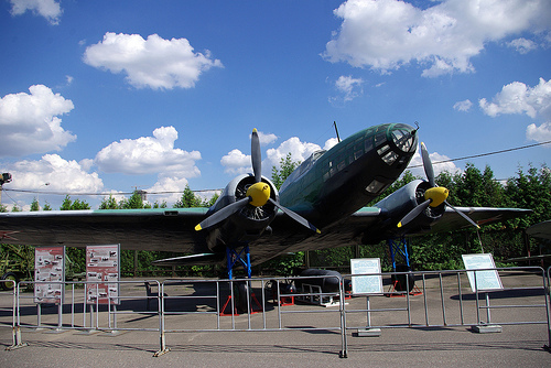
Steven F. Udvar-Hazy Center: south hangar panorama, including Grumman G-22 “Gulfhawk II”, Boeing 367-80 (707) Jet Transport, Air France Concorde amongst other folks
precision engineering company
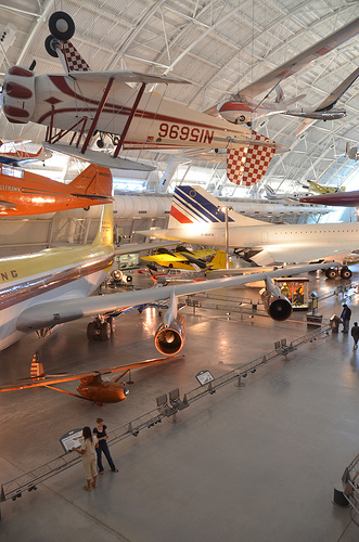
Image by Chris Devers
Quoting Smithsonian National Air and Space Museum | Grumman G-22 &quotGulfhawk II&quot:

A single of the most exciting aerobatic aircraft of the 1930s and ’40s, the Grumman Gulfhawk II was constructed for retired naval aviator and air show pilot Al Williams. As head of the Gulf Oil Company’s aviation department, Williams flew in military and civilian air shows around the nation, performing precision aerobatics and dive-bombing maneuvers to market military aviation throughout the interwar years.

The sturdy civilian biplane, with its robust aluminum monocoque fuselage and Wright Cyclone engine, practically matched the Grumman F3F regular Navy fighter, which was operational at the time. It took its orange paint scheme from Williams’ Curtiss 1A Gulfhawk, also in the Smithsonian’s collection. Williams personally piloted the Gulfhawk II on its last flight in 1948 to Washington’s National Airport.

Present of Gulf Oil Corporation

Manufacturer:
Grumman Aircraft Engineering Corporation

Date:
1936

Nation of Origin:
United States of America

Dimensions:
Wingspan: 8.7 m (28 ft 7 in)
Length: 7 m (23 ft)
Height: three.1 m (10 ft)
Weight, aerobatic: 1,625 kg (3,583 lb)
Weight, gross: 1,903 kg (4,195 lb)
Leading speed: 467 km/h (290 mph)
Engine: Wright Cyclone R-1820-G1, 1,000 hp

Supplies:
Fuselage: steel tube with aluminum alloy
Wings: aluminum spars and ribs with fabric cover

Physical Description:
NR1050. Aerobatic biplane flown by Significant Alford &quotAl&quot Williams as demonstration aircraft for Gulf Oil Business. Related to Grumman F3F single-seat fighter aircraft flown by the U.S. Navy. Wright Cyclone R-1820-G1 engine, 1000 hp.

• • • • •

Quoting Smithsonian National Air and Space Museum | Boeing 367-80 Jet Transport:

On July 15, 1954, a graceful, swept-winged aircraft, bedecked in brown and yellow paint and powered by four revolutionary new engines first took to the sky above Seattle. Constructed by the Boeing Aircraft Firm, the 367-80, far better known as the Dash 80, would come to revolutionize industrial air transportation when its created version entered service as the well-known Boeing 707, America’s first jet airliner.

In the early 1950s, Boeing had begun to study the possibility of creating a jet-powered military transport and tanker to complement the new generation of Boeing jet bombers getting into service with the U.S. Air Force. When the Air Force showed no interest, Boeing invested million of its personal capital to develop a prototype jet transport in a daring gamble that the airlines and the Air Force would acquire it as soon as the aircraft had flown and verified itself. As Boeing had done with the B-17, it risked the organization on 1 roll of the dice and won.

Boeing engineers had initially based the jet transport on studies of improved styles of the Model 367, better identified to the public as the C-97 piston-engined transport and aerial tanker. By the time Boeing progressed to the 80th iteration, the design and style bore no resemblance to the C-97 but, for security motives, Boeing decided to let the jet project be recognized as the 367-80.

Work proceeded speedily after the formal commence of the project on May 20, 1952. The 367-80 mated a huge cabin based on the dimensions of the C-97 with the 35-degree swept-wing design and style based on the wings of the B-47 and B-52 but considerably stiffer and incorporating a pronounced dihedral. The wings were mounted low on the fuselage and incorporated high-speed and low-speed ailerons as properly as a sophisticated flap and spoiler system. 4 Pratt &amp Whitney JT3 turbojet engines, each producing 10,000 pounds of thrust, had been mounted on struts beneath the wings.

Upon the Dash 80’s first flight on July 15, 1954, (the 34th anniversary of the founding of the Boeing Company) Boeing clearly had a winner. Flying one hundred miles per hour more quickly than the de Havilland Comet and significantly bigger, the new Boeing had a maximum variety of much more than 3,500 miles. As hoped, the Air Force bought 29 examples of the style as a tanker/transport soon after they convinced Boeing to widen the design and style by 12 inches. Satisfied, the Air Force designated it the KC-135A. A total of 732 KC-135s had been constructed.

Speedily Boeing turned its attention to promoting the airline industry on this new jet transport. Clearly the industry was impressed with the capabilities of the prototype 707 but in no way more so than at the Gold Cup hydroplane races held on Lake Washington in Seattle, in August 1955. For the duration of the festivities surrounding this occasion, Boeing had gathered several airline representatives to get pleasure from the competitors and witness a fly previous of the new Dash 80. To the audience’s intense delight and Boeing’s profound shock, test pilot Alvin &quotTex&quot Johnston barrel-rolled the Dash 80 over the lake in full view of thousands of astonished spectators. Johnston vividly displayed the superior strength and functionality of this new jet, readily convincing the airline industry to buy this new airliner.

In searching for a market place, Boeing located a prepared buyer in Pan American Airway’s president Juan Trippe. Trippe had been spending much of his time browsing for a suitable jet airliner to enable his pioneering firm to preserve its leadership in international air travel. Working with Boeing, Trippe overcame Boeing’s resistance to widening the Dash-80 design and style, now recognized as the 707, to seat six passengers in each seat row rather than 5. Trippe did so by putting an order with Boeing for 20 707s but also ordering 25 of Douglas’s competing DC-eight, which had yet to fly but could accommodate six-abreast seating. At Pan Am’s insistence, the 707 was produced 4 inches wider than the Dash 80 so that it could carry 160 passengers six-abreast. The wider fuselage developed for the 707 became the regular design for all of Boeing’s subsequent narrow-body airliners.

Despite the fact that the British de Havilland D.H. 106 Comet and the Soviet Tupolev Tu-104 entered service earlier, the Boeing 707 and Douglas DC-8 were larger, quicker, had greater range, and had been a lot more lucrative to fly. In October 1958 Pan American ushered the jet age into the United States when it opened international service with the Boeing 707 in October 1958. National Airlines inaugurated domestic jet service two months later making use of a 707-120 borrowed from Pan Am. American Airlines flew the very first domestic 707 jet service with its personal aircraft in January 1959. American set a new speed mark when it opened the very first frequently-scheduled transcontinental jet service in 1959. Subsequent nonstop flights amongst New York and San Francisco took only five hours – 3 hours less than by the piston-engine DC-7. The one-way fare, such as a surcharge for jet service, was 5.50, or 1 round trip. The flight was virtually 40 % more rapidly and nearly 25 % less expensive than flying by piston-engine airliners. The consequent surge of targeted traffic demand was substantial.

The 707 was initially designed for transcontinental or one-stop transatlantic range. But modified with extra fuel tanks and far more effective turbofan engines, the 707-300 Intercontinental series aircraft could fly nonstop across the Atlantic with complete payload under any conditions. Boeing constructed 855 707s, of which 725 had been purchased by airlines worldwide.

Obtaining launched the Boeing Company into the industrial jet age, the Dash 80 soldiered on as a very productive experimental aircraft. Until its retirement in 1972, the Dash 80 tested several advanced systems, many of which had been incorporated into later generations of jet transports. At one point, the Dash 80 carried three different engine types in its 4 nacelles. Serving as a test bed for the new 727, the Dash 80 was briefly equipped with a fifth engine mounted on the rear fuselage. Engineers also modified the wing in planform and contour to study the effects of diverse airfoil shapes. Numerous flap configurations have been also fitted like a hugely sophisticated method of &quotblown&quot flaps which redirected engine exhaust more than the flaps to boost lift at low speeds. Fin height and horizontal stabilizer width was later enhanced and at one particular point, a specific numerous wheel low pressure landing gear was fitted to test the feasibility of operating future heavy military transports from unprepared landing fields.

Soon after a long and distinguished career, the Boeing 367-80 was ultimately retired and donated to the Smithsonian in 1972. At present, the aircraft is installated at the National Air and Space Museum’s new facility at Washington Dulles International Airport.

Gift of the Boeing Business

Manufacturer:
Boeing Aircraft Co.

Date:
1954

Country of Origin:
United States of America

Dimensions:
Height 19′ two&quot: Length 73′ 10&quot: Wing Span 129′ eight&quot: Weight 33,279 lbs.

Physical Description:
Prototype Boeing 707 yellow and brown.

• • • • •

Quoting Smithsonian National Air and Space Museum | Concorde, Fox Alpha, Air France:

The first supersonic airliner to enter service, the Concorde flew thousands of passengers across the Atlantic at twice the speed of sound for over 25 years. Made and constructed by Aérospatiale of France and the British Aviation Corporation, the graceful Concorde was a beautiful technological achievement that could not overcome critical economic problems.

In 1976 Air France and British Airways jointly inaugurated Concorde service to destinations around the globe. Carrying up to one hundred passengers in fantastic comfort, the Concorde catered to initial class passengers for whom speed was crucial. It could cross the Atlantic in fewer than 4 hours – half the time of a traditional jet airliner. Even so its high operating costs resulted in very higher fares that restricted the quantity of passengers who could afford to fly it. These problems and a shrinking industry at some point forced the reduction of service until all Concordes had been retired in 2003.

In 1989, Air France signed a letter of agreement to donate a Concorde to the National Air and Space Museum upon the aircraft’s retirement. On June 12, 2003, Air France honored that agreement, donating Concorde F-BVFA to the Museum upon the completion of its final flight. This aircraft was the 1st Air France Concorde to open service to Rio de Janeiro, Washington, D.C., and New York and had flown 17,824 hours.

Gift of Air France.

Manufacturer:
Societe Nationale Industrielle Aerospatiale
British Aircraft Corporation

Dimensions:
Wingspan: 25.56 m (83 ft ten in)
Length: 61.66 m (202 ft three in)
Height: 11.3 m (37 ft 1 in)
Weight, empty: 79,265 kg (174,750 lb)
Weight, gross: 181,435 kg (400,000 lb)
Top speed: two,179 km/h (1350 mph)
Engine: Four Rolls-Royce/SNECMA Olympus 593 Mk 602, 17,259 kg (38,050 lb) thrust every
Manufacturer: Société Nationale Industrielle Aérospatiale, Paris, France, and British Aircraft Corporation, London, United Kingdom

Physical Description:
Aircaft Serial Number: 205. Which includes four (4) engines, bearing respectively the serial number: CBE066, CBE062, CBE086 and CBE085.
Also included, aircraft plaque: &quotAIR FRANCE Lorsque viendra le jour d’exposer Concorde dans un musee, la Smithsonian Institution a dores et deja choisi, pour le Musee de l’Air et de l’Espace de Washington, un appariel portant le couleurs d’Air France.&quot

Producing a Prototype For Your Invention

Producing a Prototype For Your Invention

Creating a prototype or a proof of notion is a essential step in taking your invention to market. To commence, if your invention is straightforward sufficient, you can produce what is know as a Frankenstein prototype. A Frankenstein prototype is a prototype that is produced with whatever you can get your hands on. It is a really rudimentary prototype that demonstrates that your invention functions at a basic level. You can use tape, glue, paper, wood, or anything around the household to get your prototype with each other. Hold in mind, this variety of prototype is not “manufacturing prepared.”

Even so, to get to a manufacturing prepared prototype, you will want to employ the skilled solutions of a product design and style and development firm. These firms will refine your prototype to make it not only prepared for manufacturing but marketable. This is the crucial word: marketable. The complete point of your invention is to not only help out mankind, but turn a profit while performing so! The item design and development firm will make your solution marketable by doing in dept evaluation such as colour combination, target marketplace evaluation, ergonomics and human aspects, and will even create turn your invention into a 3D CAD model with precise measurements and specifications to hand off to a manufacturer to run the initial production.

Another avenue is just to take your idea and sketches straight to the item design and style and improvement firm with out functioning on a Frankenstein prototype. Because it is for particular the firm will tweak and redesign elements of your original design and style, this option is a more quickly route to obtaining your invention into the marketplace.

In addition to design and improvement, item style and development firms aid inventors source companies either domestic or overseas to deal with production for you, aid locate patent attorneys to shield your invention, as effectively as a wide selection of solutions. The job of the solution style and development firm is to aid take your invention from an concept all the way to placement onto store shelves. This consists of marketing and branding services as well as analysis and field testing if essential.

Sebastian Valemont
Synthesis Labs, Inc. | Item Design and Development
8941 Atlanta Ave. #259
Huntington Beach, CA 92646
theteam@synthesislabs.com
http://www.synthesislabs.com

More Prototype China Articles

Open Cnc Method Background Revealed

According to the Shenyang Machine Tool show: in 1959, the National Science Foundation, held at New York University Assistant Professor PaulWright “for precision machining of advanced intelligent open architecture CNC method” (Machinet field 1OpenSystemAdvancedIntelligentControllerfOPrecisionMachining, MOSAIC ~ PM) project, the The project aims to discover the typical strategy utilised to make field benefit, MO, SAIC-PM shows total ‘computer-aided design (CAD), Personal computer Aided Method Arranging (CAPPY), and pc-aided manufacturing (CAM) integration typically believe that this project is the origin of open CNC program.

Shenyang Machine Tool of the early 90s of the 20th century, due to the advantages of open CNC systems, machine tool users to develop a common demand on the open architecture controller, the purpose is to acquire low-expense, higher-efficiency, interchangeable CNC method. Some machine tool manufacturers are also attempting to use Pc-primarily based CNC method to meet those requirements. Despite the fact that these numerical handle method built in? A typical computer platform earth juice, but no a lot more than their initial product of the quantity of customers has also been restricted to devoted hardware, the lead have to rely on machine tool manufacturers to give computer software upgrades and extensions. Machine tool manufacturers on the one particular hand to meet consumer demands openness, on the other hand have to adhere to the NC Department of Atmosphere of the most critical principle of robustness. Once the CNC technique to give customers with access to the capacity of the internal perform area, it might consequently result in damage to the functionality or operation of machine tool failure, whilst the machine tool makers is challenging to shirk that duty. For that reason, the professional manufacturer of CNC system is not really good on the open. Shenyang Machine Tool

open the machine tool industry has a selection of explanations. General machine tool companies in their provides open CNC method alternatives, for example, by means of on-web site adjustable servo program and user can modify the error compensation, machine tool numerical handle technique has been opened up to the finish user attributes by using the RS274 (G, M code) programming standards, to offer another level of openness, because the code makes use of regular CNC machine tool drive, so RS274 applications can be used for any 1 machine. When a business makes use of a standard interface, it is CNC method is an open, normal function modules can be interchanged. In quick, a lot of NC systems are open to some level, but couple of are open at all levels.

Open numerical manage system including hardware and application, as a result opening up the definition should satisfy each needs. Open computer software is usually a standard, free access to the module library: Open hardware is typically issued with an open input and output interfaces of the device, customers can connect through these interfaces and devices.

Of Shenyang Machine Tool above, offer a complete, universal sufficient to encourage innovation definition of open CNC technique is really crucial. The definition ought to be encouraged to open independent of specific vendors, but not difficult and fast rule modular. Open than the deposition handle technique is given the definition of a a lot more hard process is to develop a theme to meet the definition of open requirements, in order to encourage innovation, requirements have to be strictly defined interfaces suitable abstract model, and does not limit its internal implementation.

I am China Manufacturers writer, reports some data about bypass shower doors , shower splash guard.

Related Cnc Prototype China Articles

Good China Mechanical Engineering pictures

Good China Mechanical Engineering pictures

A few good china mechanical engineering images I found:

Image from web page 161 of “Railway mechanical engineer” (1916)
china mechanical engineering
Image by Web Archive Book Images
Identifier: railwaymechanica94newy
Title: Railway mechanical engineer
Year: 1916 (1910s)
Authors:
Subjects: Railroad engineering Engineering Railroads Railroad automobiles
Publisher: New York, N.Y. : Simmons-Boardman Pub. Co
Contributing Library: Carnegie Library of Pittsburgh
Digitizing Sponsor: Lyrasis Members and Sloan Foundation

View Book Page: Book Viewer
About This Book: Catalog Entry
View All Images: All Images From Book

Click here to view book on the web to see this illustration in context in a browseable on the web version of this book.

Text Appearing Just before Image:
per cent of the coal capacity of 13,300 lb. The water capacitv of the ten-der is four,800 U. S. gallons. Excellent care was essential in making the tender design and style tomeet tlie limitations of axle load as provided in the specification.In common, the locomotive was made along the lines ofAmerican practice and the builders had been offered a cost-free handin the construction of information so lengthy as they had been kept withinthe limitations of the specifications. The common dimensionsof the locomotive, as effectively as the actual weights as comparedwith the weight limitations .specified are offered in the adhere to-ing table: Engine Actual Limit of weight weight i-ront drivers 32.600 33.000 Alain drivers 32,600 33,000 Dack drivers 32,000 33.000 Total drivers 97,200 99,000 r.ngine truck 28,400 28,500 Trailing truck 30,400 31,300 Engine, total l.io,000 158,800 Tender J ront wheel 30,400 30,800 Middle wheel 30,600 30,800 l:ack wheel 30,600 30,800 Total 91,600 92,400 General Data Cage four ft. Syi in. Service Mixed luel Soft coal

Text Appearing Right after Image:
Prairie Variety Locomotive for Service in China Static wheel load. In order to come inside these call for-ments and at the very same time offer the appropriate counterbal-ance, the reciprocating parts have been made of extremely light designand a special method was employed to secure an precise ad-justment of the counterweights in the driving wheels. Thedynamic augment requirements were met and by indicates ofcareful adjustment the suitable counterbalance was securedfor the reciprocating w^eights. The boiler is of the extended wagon top tpe, radiallystayed and fitted with a combustion chamber. The locomo-tives are equipped with superheaters and the reversing mech-anism is of the Lawson patented screw t)pe, which providesfor effortless operation and is fitted with a constructive locking de-vice and an indicator which shows the exact reduce-off at whichthe engine is operated. The tender is of the six-wheel, rigid wheel base sort, witliplate side frames, the journal boxes operating in pedestalsriveted to the outdoors plates of the

Note About Pictures
Please note that these pictures are extracted from scanned page photos that may have been digitally enhanced for readability – coloration and look of these illustrations could not perfectly resemble the original function.

IL-4. Lengthy-range Soviet bomber. 1941.

IL-4. Lengthy-range Soviet bomber. 1941.

Check out these metal parts china images:

IL-4. Lengthy-range Soviet bomber. 1941.
metal parts china
Image by Peer.Gynt
Moscow. Poklonnaya Gora WWII Museum.

The Ilyushin Il-four was a Soviet Planet War II bomber aircraft, extensively utilised by the Soviet Air Force (VVS, Voenno-Vozdushnye Sily) despite the fact that not nicely known. Its NATO code-name was Bob.

Style and improvement

The Il-four started life as a quickly developed bomber prototype named the TsKB-26. Parts of the fuselage and cockpit had been taken from the TsKB-12 (Polikarpov I-16) fighter, married to new wings made of welded steel U-beams and tubes. Only a handful of have been constructed ahead of interest turned to the updated TsKB-30, which incorporated a new fuselage employing the identical construction techniques. Welding the beams essential 3 welds per joint, so the plane took a large quantity of time to develop. Nevertheless the design had outstanding variety and was really sturdy. It was put into production in 1936 as the DB-three, 1,528 getting completed by 1939.

DB-3M

DB-three was followed by the updated DB-3M, which looked comparable with the exception of a a lot bigger and a lot more rounded nose. However the plane was actually quite different internally. Making use of lessons learned from the Li-2 (Douglas DC-3) the entire plane was re-built making use of T shaped formers rather of the tubes and U-beams. This led to a tremendous reduction in the time needed to develop the plane, and the DB-3M was hurriedly put into production.

DB-3F / Il-four
A modify of engine from the 708 kW (950 hp) M-87B to the 820 kW (1,100 hp) M-88 resulted in the DB-3F, which had been sooner or later renamed in 1942 as the Il-4. Some series had wooden outer wings and front fuselage to conserve metals, and throughout the production engines and fuel tanks had been upgraded for more overall performance whilst keeping the very same range. However the most notable adjust was the addition of larger defensive guns in the turret, making use of the 12.7 mm (.5 in) UBT in location of the earlier 7.62 mm (.3 in) weapons. In addition it was found that the gunners have been attacked initial, so blocks of armor were placed around the gunner positions.

All this added weight wasn’t offset by the newer engines nonetheless, and the Il-4 proved to be slower than the earlier versions at only 404 km/h (251 mph). An try to enhance efficiency was made as the Il-six, adding big diesel engines and heavier armament. The engine proved unreliable and production was in no way began. The Il-four remained in production until 1944, when just over five,200 had been constructed.

Operational history
Although the Il-four was only a medium bomber, it had the variety to be utilized on strategic missions. The VVS wasn’t terribly interested in this part, but nevertheless the Il-four was utilized on many very publicized raids against Berlin. Most would be used on significantly shorter variety missions, frequently adding one more 1,000 kg (2,204 lb) of bombs under the wings, in addition to the internal 2,500 kg (five,512 lb).

Finland bought four captured DB-3Fs from German stocks. These were offered the Finnish Air Force serials DF-22 to DF-25 and flown from Bryansk, Russia to Finland (a single aircraft, DF-22, was destroyed en route and crashed near Syeschtschinskaya airfield). The aircraft had been later flown by No. 48 Sqn during 1943 (DF-23, DF-24 and DF-25), No. 46 Sqn for the duration of 1944 (DF-23 and DF-24) and No. 45 Sqn for a short time in 1945 (DF-23), until the final remaining serviceable aircraft went into depot, February 23 1945[2]

Operators

China
Chinese Nationalist Air Force 24 aircraft
Finland
Finnish Air Force 11 aircraft of the type DB-3M and 4 aircraft of the sort DB-3F (Il-four)
Germany
Luftwaffe
Soviet Union
Soviet Air Force
Soviet Naval Aviation

Specifications

Il-four at Moscow This aircraft write-up is missing some (or all) of its specifications. If you have a source, you can help Wikipedia by adding them.

General traits

Crew: four (pilot, navigator, gunner/wireless-operator, rear gunner)
Length: 14.80 m (48 ft six.75 in)
Wingspan: 21.44 m (70 ft four.five in)
Height: 4.ten m (13 ft five.five in)
Wing region: 66.7 m² (718 ft²)
Empty weight: five,800 kg (12,787 lb)
Max takeoff weight: 11,300 kg (24,912 lb)
Powerplant: 2× Tumansky M-88B radial engines, 820 kW (1,100 hp) each and every
Overall performance

Maximum speed: 430 km/h (232 kn, 267 mph)
Range: 3,800 km (2,052 nmi, 2,361 mi)
Service ceiling: 9,700 m (31,825 ft)
Armament

two × 7.62 mm ShKAS machine guns
1 × 12.7 mm Berezin UB machine gun
Up to two,500 kg (5,500 lb) of bombs or mines. Alternatively, 1 × 940 kg (two,072 lb) 45-36-AN or 45-36-AV torpedo. Really rarely, 2 × BETAB-750DS 305 mm rockets[3].

Thames Festival Finale Fireworks
metal parts china
Image by Dominic’s pics
Portion of a Set / Virtual Firework Show Slideshow documenting the firework show that marked the finish of the &quotthe mayor’s&quot Thames Festival in London on the evening of Sunday September 11th 2011.

The display was presented by Pains Fireworks.

A delay in the commence of the display from the scheduled time was attributed by the crowds to incompetence by &quotBumbling Boris&quot Johnson – the London Mayor – portion of the British patrician &quotlimited liability&quot ruling class. &quotI’m in charge, but if anything goes incorrect, somebody else will be sacked…&quot

Like the extreme audio dynamic variety of Taiko or Samba drumming, it is not truly attainable to record the visual brilliance of fireworks with a camera. You have to encounter firework displays live, in particular person. These images had been taken at the slowest sensor speed (ISO 100), maximum aperture (to minimise diffraction &quotglare&quot effects) and with a assortment of exposure times ranging from about .5 to 2 seconds. The intense light caused some &quotbleaching&quot of the paths of the lights, and so the colours have been enriched if Photoshop. (In retrospect I may well have employed a slightly smaller sized aperture.)Furthermore, the river and land regions have been selectively lightened in Photoshop. Fortuitously, a gentle breeze brought on the smoke to drift eastwards, away from my vantage point on Waterloo Bridge, so the view of the fireworks was reasonably unobstructed by smoke.

Fireworks date from at least the 7th century in China. The colours are believed to have been traditional incandescent &quotblack body&quot bonfire colours: red, orange, yellow and white. (It is theoretically achievable to create pale blue just by heating, but this requires impracticably higher temperatures. It is not achievable to heat one thing to &quotgreen hot&quot or &quotpurple hot&quot.) It is believed that from about 1830 in Italy metal salts had been introduced to produce a wider, richer hued, spectrum of colours by chemical luminescence. This approach can be problematic, as it can be hard to produce steady, sensible, chemical compositions. It has been recommended that some shades of green are nonetheless hard to achieve.

See also:

Fireworks [Wikipedia]
Firework Colours [The chemistry of Fireworks by Reema Gondhia, Imperial College]
History of fireworks [Pyro Universe]

Thames Festival Weekend Finale Fireworks
metal parts china
Image by Dominic’s pics
Part of a Set / Virtual Firework Display Slideshow documenting the firework show that marked the finish of the &quotthe mayor’s&quot Thames Festival in London on the evening of Sunday September 11th 2011.

The display was presented by Pains Fireworks.

A delay in the start of the display from the scheduled time was attributed by the crowds to incompetence by &quotBumbling Boris&quot Johnson – the London Mayor – component of the British patrician &quotlimited liability&quot ruling class. &quotI’m in charge, but if something goes wrong, somebody else will be sacked…&quot

Like the extreme audio dynamic variety of Taiko or Samba drumming, it is not really possible to record the visual brilliance of fireworks with a camera. You have to knowledge firework displays live, in person. These pictures had been taken at the slowest sensor speed (ISO one hundred), maximum aperture (to minimise diffraction &quotglare&quot effects) and with a variety of exposure occasions ranging from about .5 to 2 seconds. The intense light caused some &quotbleaching&quot of the paths of the lights, and so the colours have been enriched if Photoshop. (In retrospect I may have utilized a slightly smaller sized aperture.)Furthermore, the river and land places have been selectively lightened in Photoshop. Fortuitously, a gentle breeze brought on the smoke to drift eastwards, away from my vantage point on Waterloo Bridge, so the view of the fireworks was reasonably unobstructed by smoke.

Fireworks date from at least the 7th century in China. The colours are believed to have been conventional incandescent &quotblack physique&quot bonfire colours: red, orange, yellow and white. (It is theoretically attainable to generate pale blue just by heating, but this needs impracticably higher temperatures. It is not attainable to heat anything to &quotgreen hot&quot or &quotpurple hot&quot.) It is believed that from about 1830 in Italy metal salts have been introduced to produce a wider, richer hued, spectrum of colours by chemical luminescence. This approach can be problematic, as it can be tough to generate steady, practical, chemical compositions. It has been recommended that some shades of green are nevertheless hard to accomplish.

See also:

Fireworks [Wikipedia]
Firework Colours [The chemistry of Fireworks by Reema Gondhia, Imperial College]
History of fireworks [Pyro Universe]

Cool Machining Engineering images

Cool Machining Engineering images

Some cool machining engineering pictures:

Machine
machining engineering
Image by MattyGregs

scary
machining engineering
Image by John Christian Fjellestad

Skull fabric
machining engineering
Image by Cross-stitch ninja
Crappy, crappy mobile telephone pic, but I am so excited about this! It was the very first time we had been permitted to use the huge knitting machines at school!
We did everything, from designing the pattern to setting the machine. This is what I’ve been waiting for given that I decided to start off studying again.

Cool Machining Engineering images

Cool Machining Engineering images

Some cool machining engineering pictures:

Image from web page 485 of “American engineer and railroad journal” (1893)
machining engineering
Image by World wide web Archive Book Photos
Identifier: americanengineer68newy
Title: American engineer and railroad journal
Year: 1893 (1890s)
Authors:
Subjects: Railroad engineering Engineering Railroads Railroad cars
Publisher: New York : M.N. Forney
Contributing Library: Carnegie Library of Pittsburgh
Digitizing Sponsor: Lyrasis Members and Sloan Foundation

View Book Web page: Book Viewer
About This Book: Catalog Entry
View All Photos: All Pictures From Book

Click right here to view book on-line to see this illustration in context in a browseable on the internet version of this book.

Text Appearing Before Image:
qually satisfactory. The tiny enginedrives drills and valve-facing tools straight by implies of theStow flexible shaft. The identical practise also prevails here, ason the other road, in the building of pistons. A hollowpislon with rings sprung in is employed, but the rings are muchnarrower than on the New York, Lake Erie &amp Western. Mr.Foster makes use of a ring only | in. wide, and finds them perfectlysatisfactory. There is a strategy of holding the split rings out 496 THE AMERICAN ENGINEER [November, 1894. right here, nonetheless, that—to us at least—is novel. It is well knownthat if a ring is turned to a bigger diameter than that of thecylinder in which it is to run, when it is sprung in it will beout of round. To obviate this difficulty and, at the same time,hold an outward pressure on the ring, it is turned to match thecylinder. Yet another and slightly heavier ring is turned to adiameter a trifle bigger than the inside of the outer ring, andthe outer ring slipped more than it. Then, wheu they are both com-

Text Appearing Soon after Image:
BALANCED VALVE, FALL BROOK COAL CO. pressed and place in thecylinder, the outer ring is round, whilethe inner keeps it nicely out against the walls. The vehicle shops adjoin the machine shop, and are fitted withthe usual complement of woodworking tools. The floor roomconsists of three tracks, each capable of holding 5 automobiles. AllCars coming in for rebuilding and all new rolling stock areequipped with the Gould coupler and the Westinghouse airbrake. The nicknames bestowed up-on a variety of varieties of locomotivesby the men constructing or runningthem have come to have a trulytechnical significance but it is sel-dom that a nickname is acceptedby the motive energy departmentwith the gravity of a name appliedto one particular of the locomotives on thisroad. All the engines have namesas nicely as numbers, although theformer are a mere ornament andnot used in reports or orders. Acertain locomotive had the misfor-tune to jump from a high trestle atIthaca, and was forthwith dubbedthe Sam Patrh by the males. Re-pairs naturally

Note About Pictures
Please note that these pictures are extracted from scanned page images that might have been digitally enhanced for readability – coloration and appearance of these illustrations may possibly not completely resemble the original work.

Image from page 423 of “Manual for railroad engineers and engineering students : containing the guidelines and tables necessary for the location, building, and equipment of railroads as constructed in the United States” (1883)
machining engineering
Image by Web Archive Book Pictures
Identifier: manualforrailroa00vose
Title: Manual for railroad engineers and engineering students : containing the rules and tables needed for the place, building, and equipment of railroads as constructed in the United States
Year: 1883 (1880s)
Authors: Vose, George L. (George Leonard), 1831-1910
Subjects: Railroad engineering
Publisher: Boston : Lee and Shepard
Contributing Library: Northeastern University, Snell Library
Digitizing Sponsor: Northeastern University, Snell Library

View Book Page: Book Viewer
About This Book: Catalog Entry
View All Images: All Pictures From Book

Click right here to view book on-line to see this illustration in context in a browseable on-line version of this book.

Text Appearing Before Image:
Fig- 157- Fig. 157 and the addition of a related truck behind gives thetank engine, made by Mr. Hudson, of the Rogers Locomotive 398 MANUAL FOR RAILROAD ENGINEERS. Functions, shown in Fig. 158, a most excellent machine for switching,construction, branch, and even light passenger service.*

Text Appearing Soon after Image:
Fig. 158. Iig- 1S9 shows a six-wheeled tank engine, which, upon a toler-ably straight track, is a quite effective machine, but upon sharp

Note About Images
Please note that these images are extracted from scanned web page photos that may possibly have been digitally enhanced for readability – coloration and look of these illustrations may not completely resemble the original work.